Search the Community
Showing results for tags 'data matching software'.
Found 183 results
-
Hi, i am currently looking for a software that can open .gop-projects so i can look in the code and upgrade some panels at my current customers place. This software and GOP2000 are ancient and have not had any reply from ABB for several days about this. The GOPs here is starting to fail and we only got 1 spare that are in service almost 24/7.
-
I am trying to program an analogue output on a Siemens S7-1500 unit from a 4-20ma sourced analogue input scaled over 0-250 degrees. The analogue input will have an adjustable setting in the software for when the alarm status should occur and at this point I want the analogue alarm output to start to process at 4ma, at 5 degrees above the initial set point I want the analogue output value to be 20ma I have no idea how to do this so any help from people is greatly appreciated and advice on which analogue output card to use would be helpful.
-
Hello Experts, I have recently started to learn about PLC and Industrial Automation. I got Logo Soft Comfort demo software which cannot communicate with the hardware. How/Where (link) can I get a full version 8 of Soft Comfort for free? Thanks.
-
 There have been many good discussions on the applicability of cloud-based solutions for manufacturing and process control systems. On one side, some people have concerns regarding security and control of the information, on the other side, there are identified benefits enabled by cloud systems. From VMS minicomputers to DOS and Windows, from ArcNet to Ethernet, it is inevitable the industrial automation systems shall adopt the technologies that are getting predominant in IT general use; the current environment that I am calling the “Cloud-iPad era” is no different; therefore the practical discussion is not if those new technologies will be applied in the industrial environment, but how. This paper is not intended to join the conceptual discussion about the cloud, but just to present a few simple practical examples, where cloud technologies are already enhancing industrial automation solutions and enabling new business opportunities. CloudPracticalApplications.pdf
 -

Send data memory from PLC to other PLC with CX Programmer
Amsterdamstyle posted a topic in CX-Programmer
Hello people, I hope someone can help me with this. The system is connected with 8 PLC's. I want to transfer the data memory of a PLC to another like this: D850 from PLC2 to D900 PLC1 D850 from PLC3 to D901 PLC1 D850 from PLC4 to D902 PLC1 D850 from PLC5 to D903 PLC1 D850 from PLC6 to D904 PLC1 D850 from PLC7 to D905 PLC1 D850 from PLC8 to D906 PLC1 The data memory is an integer. -
hello,,,, i want to ask, is there a way to convert the yaskawa PLC ladder program to a Mitsubishi PLC? and what software is used to program PLC brand of YASKAWA?
-
Hello, Completely new to Mitsubishi PLCs and I need to use a date and time stamp for data collection purposes. We have a Siemens PLC as well and this has the data type "Date_And_Time" which is what I need to replicate. I have been attempting to write my own data type but am struggling with how to go about this as it is not straightforward and I cannot find anything about how the Siemens Date_And_Time is made up so I have nothing to go off. Does anyone have an example of a data type they have made that is the same? Or is there a data type which does this already in GX Works 2 that I just can't seem to find? Please help!
-
Hello,, I have motion controller A series A172SHCPUN,, I have written the program ladder into the CPU, but I can't write the motion program.. i dont have the program to open file the program motion and I want to ask if I have the software SW3RNC-GSVE, my os computer is window XP, Can it be installed? and is the cable transfer used the same as the ladder transfer program cable (SC09)?
-
Hi Everyone, I would like to know if two S7-300 CPU can exchange data via MPI protocol using X_Put and X_Get blocks. is it possible to test the data exchange via PLCSIM to verify. CPU1 = 313C-2DP CPU2 = 312 Please advise. Thank you.
-

S7A driver shows same values for different inputs in data monitor
horvatmiha posted a topic in Siemens
Hello! I am beginner in PLC world, also in SIEMENS PLCs. I managed communication over private network. Now I have a problem that I get same values on all inputs. Picture below shows my configuration of driver and data monitor. First picture shows values when input I0.0 is in state 0. Second picture shows values when input I0.0 is in state 1. Physically on PLC only input I0.0 is forced to 1, input I0.1 stays 0. But data monitor shows both inputs as state 1. Where is problem? Is problem in PLC program, TIA portal? I saw some guys using DataBlocks but I am not skilled enough to use it. Third picture shows simple PLC program on my PLC. Please help. Thanks in advance! -
Version V2.2.5
57 downloads
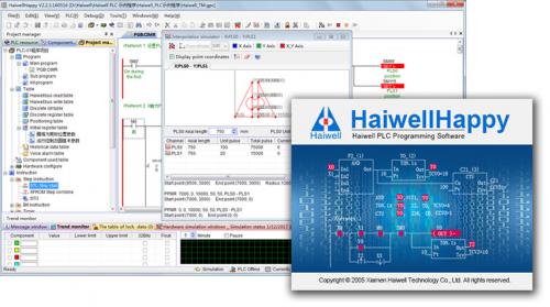
HaiwellHappy Programming Software Features HaiwellHappy is the programming software for Haiwell PLC. It accordance with IEC 61131-3 standard, supports built-in simulator and three kinds of programming languages (LD-Ladder Diagram, FBD-Function Block Diagram and IL-Instruction List). It can run on the systems of Windows 98, Windows 200X, Windows XP and the later Windows versions. ** You can get the latest version from Download center for free ** HaiwellHappy Features l Haiwell Cloud Programming Support Haiwell Cloud platform, can use Haiwell cloud to do remote programming for Haiwell PLC as upload/download, firmware upgrading, self-diagnosis, monitoring and debugging. Easy for remote connection and real-time data monitoring of the site. Also you can do local programming through a HMI which supports built-in cloud engine. l Built-in PLC simulator Haiwell PLC programming software supports internal simulator, realizing the PLC program run in the simulation. During programming or the programming is completed, you can run PLC program in the simulation without online to check the program execution is correct or not. It can reduce on-site commissioning time greatly, reduce debugging difficult and improve debugging efficiency. l Communication simulator It is used to the debug communication instruction simulation tools. It can be manually input simulately response message returned from salve, or you can use the computer's serial port to communicate with salve really, Simulate the process that PLC executes communication instruction really and process the return data from the salve. l Interpolation simulator Track and draw the trajectory generated from motion control instructions such as the linear interpolation, circular interpolation, listing parameters of the pulse output channel of the motive plane and corresponding to each axis, display the current position of the channel, the mechanical home position, output mode, you can set shaft length, unit pulses. l PLC executable file Generation PLC program can be generated to executable file which is released and executed independently. So you do not need to send the PLC program to the user, it can be very easy, very safe to put the PLC excutable file to the user to download, but do not worry the user would can see the program content. l Innovative convenient instruction sets On the basis of analysis and absorption of various PLC instruction, Haiwell PLC launched many powerful innovations facilitate instruction. As communication instruction (COMM, MODR, MODW, HWRD, HWWR), data portfolio diversification instruction (BUNB, BUNW, WUNW, BDIB, WDIB, WDIW), PID control (PID), valve control (VC), upper and lower alarm (HAL, LAL), range transmitter (SC), temperature curve (TTC) etc. Any one instruction can realize the function but other PLC required to multiple instructions. These instructions are very easy to understand and use, greatly improve the programming efficiency and running speed. l Modular project structure Create 63 blocks total (main program, sub program, interrupt program) and chose any programming language to program. The execution order of block can be adjusted at random. Each block can be imported and exported independently and has the same password protected of program projects. So we can fully realize the modular programming and program reuse dreams. l Convenient instruction form Provides multiple instruction tables. Use these tables can reduce the amount of programs, saving program space, such as initialization data. Each table can be imported and exported independently and has the same password protection of program project. l Powerful online networking Search out all the PLC that connect with the PC. Show running status, fault status, RUN / STOP switch position, hardware configuration information, communication port parameters such detailed information of all the online PLC. Select any PLC for online monitoring, program download, firmware upgrade, controlling PLC stop, adjusting PLC real-time clock, modifying password protection, modifying communication port parameters, modifying the watching-dog time and PLC station names. l Online monitoring and debugging functions Provide 10 pages of component’s monitoring table. It can choose in decimal, hexadecimal, binary, floating point and character to display data. Support component and register component monitoring hybridly and displaying component annotation at the same time. All instruction tables can be imported to the monitoring table. l Unique real-time curve functions Monitor any of the register elements of its real-time curve, convenient to control and debug during the process. l User friendly input method Provide shortcuts, drag and drop, click and many other command input. Suggest effective components or range of values for each input and output terminals. It can be entered directly. Some data of combination (such as communication protocols etc.) can also double-click the instruction to configure the input data. l Convenient annotation Provide the component comment, network comment, instruction comment, block comment, table comment, and project comment. After the component with “//” to input comments directly (e g.: X0 // motor start).Comments can choose to download to the PLC for reading or modification facilitately. l Detailed tips and online helps Provide PLC resource window, instruction window, etc. All the instructions and detailed description of hardware modules can be found in powerful online help system which is open through clicking F1 key in the programming interface to find the answer. Even if use HaiwellHappy programming software for the first time who can easily complete the preparation of control program. l Convenient editing functions Support all conventional editing operations, searching and replacing, instruction up and down, network up and down, copying and pasting between program projects. l Hardware configuration, sub program parameter passing, local components, indirection, print, preview, debugging, CRC calculation, password protection, etc. -
[Other PLC Demo Software] - Haiwell PLC programming software- HaiwellHappy
Haiwell posted a topic in Download Comments
Haiwell PLC programming software- HaiwellHappy View File HaiwellHappy Programming Software Features HaiwellHappy is the programming software for Haiwell PLC. It accordance with IEC 61131-3 standard, supports built-in simulator and three kinds of programming languages (LD-Ladder Diagram, FBD-Function Block Diagram and IL-Instruction List). It can run on the systems of Windows 98, Windows 200X, Windows XP and the later Windows versions. ** You can get the latest version from Download center for free ** HaiwellHappy Features l Haiwell Cloud Programming Support Haiwell Cloud platform, can use Haiwell cloud to do remote programming for Haiwell PLC as upload/download, firmware upgrading, self-diagnosis, monitoring and debugging. Easy for remote connection and real-time data monitoring of the site. Also you can do local programming through a HMI which supports built-in cloud engine. l Built-in PLC simulator Haiwell PLC programming software supports internal simulator, realizing the PLC program run in the simulation. During programming or the programming is completed, you can run PLC program in the simulation without online to check the program execution is correct or not. It can reduce on-site commissioning time greatly, reduce debugging difficult and improve debugging efficiency. l Communication simulator It is used to the debug communication instruction simulation tools. It can be manually input simulately response message returned from salve, or you can use the computer's serial port to communicate with salve really, Simulate the process that PLC executes communication instruction really and process the return data from the salve. l Interpolation simulator Track and draw the trajectory generated from motion control instructions such as the linear interpolation, circular interpolation, listing parameters of the pulse output channel of the motive plane and corresponding to each axis, display the current position of the channel, the mechanical home position, output mode, you can set shaft length, unit pulses. l PLC executable file Generation PLC program can be generated to executable file which is released and executed independently. So you do not need to send the PLC program to the user, it can be very easy, very safe to put the PLC excutable file to the user to download, but do not worry the user would can see the program content. l Innovative convenient instruction sets On the basis of analysis and absorption of various PLC instruction, Haiwell PLC launched many powerful innovations facilitate instruction. As communication instruction (COMM, MODR, MODW, HWRD, HWWR), data portfolio diversification instruction (BUNB, BUNW, WUNW, BDIB, WDIB, WDIW), PID control (PID), valve control (VC), upper and lower alarm (HAL, LAL), range transmitter (SC), temperature curve (TTC) etc. Any one instruction can realize the function but other PLC required to multiple instructions. These instructions are very easy to understand and use, greatly improve the programming efficiency and running speed. l Modular project structure Create 63 blocks total (main program, sub program, interrupt program) and chose any programming language to program. The execution order of block can be adjusted at random. Each block can be imported and exported independently and has the same password protected of program projects. So we can fully realize the modular programming and program reuse dreams. l Convenient instruction form Provides multiple instruction tables. Use these tables can reduce the amount of programs, saving program space, such as initialization data. Each table can be imported and exported independently and has the same password protection of program project. l Powerful online networking Search out all the PLC that connect with the PC. Show running status, fault status, RUN / STOP switch position, hardware configuration information, communication port parameters such detailed information of all the online PLC. Select any PLC for online monitoring, program download, firmware upgrade, controlling PLC stop, adjusting PLC real-time clock, modifying password protection, modifying communication port parameters, modifying the watching-dog time and PLC station names. l Online monitoring and debugging functions Provide 10 pages of component’s monitoring table. It can choose in decimal, hexadecimal, binary, floating point and character to display data. Support component and register component monitoring hybridly and displaying component annotation at the same time. All instruction tables can be imported to the monitoring table. l Unique real-time curve functions Monitor any of the register elements of its real-time curve, convenient to control and debug during the process. l User friendly input method Provide shortcuts, drag and drop, click and many other command input. Suggest effective components or range of values for each input and output terminals. It can be entered directly. Some data of combination (such as communication protocols etc.) can also double-click the instruction to configure the input data. l Convenient annotation Provide the component comment, network comment, instruction comment, block comment, table comment, and project comment. After the component with “//” to input comments directly (e g.: X0 // motor start).Comments can choose to download to the PLC for reading or modification facilitately. l Detailed tips and online helps Provide PLC resource window, instruction window, etc. All the instructions and detailed description of hardware modules can be found in powerful online help system which is open through clicking F1 key in the programming interface to find the answer. Even if use HaiwellHappy programming software for the first time who can easily complete the preparation of control program. l Convenient editing functions Support all conventional editing operations, searching and replacing, instruction up and down, network up and down, copying and pasting between program projects. l Hardware configuration, sub program parameter passing, local components, indirection, print, preview, debugging, CRC calculation, password protection, etc. Submitter Haiwell Submitted 03/18/19 Category Other PLC Demo Software -
Hello all I have OMRON PLC CP1E-E10DR-A. I installed CX programmer , where I unable to connect the PLC.Driver successfully installed. In the software , i unbale to connect, there is no option for choosing E10DR, Th software has option of choosing E20 and above. Can anybody help in this? Thanks
-
Dear all I am very new to PLC and having knowledge in embedded C program.I would like to start learning PLC programming. I have OMRON CP1E-E10DR-A , It detected in my computer. I want suggestion recommendation on that which software will be chosen to work with this PLC. Please help me. Thanks
-
Lets say I worked in a factory that made multiple models of parts. I need to run data tracing on the off shift due to certain models only running on 2nd and 3rd shift. I want one data trace to capture one group of bits at Model 1, Then reset the Data Points and run again for Model 2, Model 3 and so on. So the Bits that I am mapping with the trace need to change. I can change the trigger easy enough with my program. I see in the manual the CPU has a "separate memory area" for trace settings. Can this area be accessed from the Program so I can set my bit addresses to monitor to a word or E_? See attached pic for clarification of what I aim to change through the program.
-
I have the following for sale. I would prefer to sell as a lot. I can send pics if there is any interest. EX40 + 20 IO Extension with 2 Unused output PCB for ext unit. 2 EX40 Plus PLC. Timer Counter access unit Operational. With 2 PCB with errors showing. Handheld Programmer (Squeekbox) excellent condition. CutlerHammer Original software with hardware dongle. Some spare parts, they were operational before I used for testing various functions. PM ME IF ANY INTEREST.
-
Modbus addressing in Weintek HMI to poll data from Temperature sensor through RS485. In my system i have connected Temperature sensor to I/O Scanner has output in terms of RS-485 which directly connected to COM3 Port pin. No. 6 (as Negative) & 9 (as Positive) of HMI (Model No: MT8071iE) and HMI connected to PC via ETHERNET. I want to read temp on HMI screen via MODBUS protocol. So, can you please provide me instruction about addressing of MODBUS register in Easy-Builder Software so can read data of corresponding register. Because when i do compile i got an error like " Device no Response". I hope i will get reply from your side as Fast as possible to overcome this problem. Thank you.
-
Dear All, I am having a problem with my cimplicity Auto Report Generation, When I Click on Generate Report, it shows "0 values collected" does anyone knows what's possibly could gone wrong here ??
-
Hello, everyone. I want to ask for help.. i want to upgrade HMI hakko V7 to V9.. have file hmi in V7 use software V-SFTV5 but when I open file V7 use software V-SFTV6 its cant convert and i attached the screenshoot below.. can someone tell me what's wrong?
-
Where would I find TC_2PID_Function_BLOCK? as described in the Temperature Regulation Solution, Quick Start Guide v1.02 Is there somewhere on the omron web site to find all up to date FB Libraries?
-
Hello all ... i am a new plc user.. i am using D500 for taking value as it is a latched register. i am taking value for a flow meter. i have two questions. 1. how totalizer is calculated from flow rate as my flow rate is in m3/h. 2. the value of register is gone upto 32000 approximately... i want that this value to go on.. i mean how 32 bit register is declared in plc .. a
-

Modbus address register exchange between Melsec-Q series PLC and ME96SSHA-MB Power meter
RV3.0 posted a topic in Mitsubishi
Please assist me with the following; regarding the ME96SSHA-MB Power meter data transition with Melsec-Q series PLC; We acquire to read various values on dedicated Modbus storage address registers at the simultaneous into a Melsec-Q series PLC via Modbus (TCP or RTU) for calculation purposes. Naturally, since the reading of these variables are to provide accurate instantaneous results, it is a requirement that these values are to be read at one scan. However, as can be seen below, there is a gap in address register range – of which, if all of these are scanned simultaneously, yields an exception error when read. This error is only avoided by scanning these data sets separately – which is not ideal for our application – since accuracy in calculations is imperative. -
Hello I have been using GX Works 3 for a while now and I have discovered a couple of things, maybe bugs. I have not had any training for the software or hardware so maybe I did something wrong. 1 Labels. If you sort a global label table into any order other than the unsorted order that appears by default you are unable to create, delete or edit any labels. Our Mitsubishi representative discovered that if you click on the column header between 'Data Type' and 'Class' the order does not change but now editing is available. This, it turns out is a really bad idea. It seems the position the label was in when it was created is preserved, I think this is the unsorted order you get by default. If you sort the list and then delete a label it is possible that the label that should be in that position is also deleted. I have attached a small project to demonstrate this. Open the Global Labels notice the order they were created. Now change the sort order, click on the column header I described earlier to make them editable and then delete the label in position 1. For a while I thought this was the only problem but recently there has been a number of instances where I have created a label, given it a carefully selected address only to discover that it is being overwritten by another variable. I have not been able to work out exactly what is going on but I believe it is connected to the sort order of the labels. Also if you sort the order and change an address, have you changed the address of another label? The only solution I have found is to keep label tables very short so they are managable without having to sort the order, that is probably good practice anyway 1 Axis software limits. I have been using a number of axes in pairs, in incremental mode as caterpillar feeders, using FX5U-40SSC simple motion modules. I had a problem that the axis synchronised to follow would suddenly stop moving, the customer was having to power down the machine and start again. This problem persisted for months with Mitsubishi scratching their heads unable to fathom it out and ultimately stating that the problem must be in my code somewhere. It was suggested by the customer that it may be getting to a software limit, I showed the customer that the software limit was disabled in the setup and it was confirmed by Mitsubishi that it was not the problem. guess what, it is a problem. Once the actual position reached the limit of the double word memory it would stop moving. The solution is the take the servos out of synchronisation in order to set the position (datum) to zero every cycle. Unfortunately the drives do not always re-synch on the first attempt so you have to keep trying till it does, this now causes slight variations in cycle times but it works. Andy EDIT: I have since been informed that to disable the software limits they must be set to zero. This implies that the Enable/Disable setting is invalid and the limits are defaulted to their respective max values. Surely a default to zero would be more appropriate. Label Test.gx3
-
My apologies for being a newbie on this, but could someone save me on this... I have a Viper 650 and an eMB-60R controller which I want to control by ePLC connection using an NJ501-1300 PLC unit, SYSMAC Studio with EIP Adept Library for Robot... All are starting up well, and I connect all components to a switch hub... But following the ePLC guidelines, the IP Address showing on the controller is 172.16.132.111 I change the IPV4 IP Address on the PC settings to 172.16.132.10 and the subnet to 255.255.0.0 but the Adept IP Address Setting Tool on SYSMAC doesn't detect the Robot IP Address, also i tried ipconfig on command prompt which shows a different IP Address IPV4 169.254.197.75 and subnet of 255.255.0.0, I changed the previous setting on the PC setting to 169.254.197.10 with the same subnet. But still PC doesn't recognize. I tried both configurations if ACE Software can detect it but the same ACE can not detect it also... Appreciate any thoughts on what's wrong in my configurations. Thank you.

.jpg.ab4bdacbd75415ee4a44ee0400895a6a.thumb.jpg.83cdde1f1a77c9aa8bca447d6c02783b.jpg)