Search the Community
Showing results for tags 'counter card'.
Found 67 results
-
Hi everyone, I need some help with my PLC programming. I am currently using a twincat 2 software and a Beckhoff CX 8090. Basically, the gist of my program is to send and receive data and datalog the input data received from the sensors and timestamp the received data for every 1 second. I want to create a boot up counter where it will count the number of times my data logging program has restarted(if it did). This boot up counter serves as a health monitoring check to ensure that my program is running perfectly and thus, not restarting randomly when it shouldn't. I am more familiar with structured text so if you have a solution, kindly post it in structured text form. Your help would be greatly appreciated. Best regards, DeadPool
-
Hello, My quest is to make a memory card, which I can just put into my PLC on the field and load all program and options etc to my plc. Now i found the official omron guide about it but its not good at all... For example is does not explain that how i need to transfer the H and D memory part to the plc, and that not all network settings are being copied if im not careful. But my question is: is it possible to make this backup memory card without having the actual plc? Because the process is done in memory card window, which is only available if you are online. So basicly i have to get all the plc rack parts to make this work? I tried with the simulator but ofc it is not working. Someone mentioned me that it is possible he heard from someone but no one actually knows how to. And there is nothing in the omron manual as i see.
-
Hi guy ! I have a problem with plc omron cp1e.Please every body help me. I was used high speed counter to count clock of encoder. And I want to count up/down pulse input case.But it not excuted.also if i use pulse + direction them it ok I used CX programmer. Thanks all
-
I have read that it is possible, in CXDesigner, to download the program from the computer onto a memory card, and then download from the memory card into the HMI terminal. Is a similar thing possible with CXProgrammer, and PLCs? It would be quite useful, for the purposes of updating the program on a customer PLC that is located overseas, when the customer does not own a laptop with CXProgrammer installed.
-
Hi, I keep getting an error that project is in binary mode and plc is in BCD mode. Wont let me change either. I must be trying in the wrong place...please point me to where i can change this in the PLC. I am getting an error in my RXDU with a Honeywell barcode reader, on one machine, I am thinking it is related. thanks for any help.
-
Hi: I urgently need a simple sample Counter Interrupt Program to study and implement with my machine. I am using GX Work 2 My Problem is inconsistent start stop of roller conveyor after pulse count (OUT_C_32, with cc235, using CC235 to stop a conveyor.) I have to try interrupt, but the manual sample is suck! Please help Tks
-

How to use analog values in SoMachine Basic?
mgn posted a topic in Modicon / Telemecanique / Schneider Electric
I'm using TM221CE40T PLC with TM3DI16 DI extension. I'm programming it using SoMachine Basic. In the program I implemented a counter (%C0). I've read in the documentation that %Ci.V stores the current count value. I want that to display this value on a Magelis HMIS5T. How could I store the current count value (%Ci.V)? Thanks in advance! -
hi: in Omron that is a command to count how many bit that are in ON state, any similar instruction in GX Work 2? Thanks
-
Version 1.0.0
208 downloads
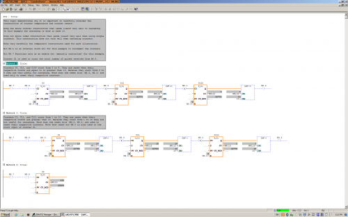
This logic demonstrates the construction and cascading of counters that count from 0 to 9. This logic also illustrates the construction of counters that count from 1 to 10 (not useful for cascading). The difference is mainly in the comparators used to reset the counters. There is one small additional detail. Can you find it? -
View File FC3 Counter Demo This logic demonstrates the construction and cascading of counters that count from 0 to 9. This logic also illustrates the construction of counters that count from 1 to 10 (not useful for cascading). The difference is mainly in the comparators used to reset the counters. There is one small additional detail. Can you find it? Submitter pop29684 Submitted 03/24/16 Category PLC Sample Code
-
SOE card compatibility with Quantum & premium PLc
pankajgandhi@y7mail.com posted a topic in Modicon / Telemecanique / Schneider Electric
Is SOE card compatible with both quantum & premium plcs.? -
Hello, I hope you are all having a great Wednesday. So I was wondering if this is possible, and if so, how to do it. What I'm trying to do is get a real time speed of my hydraulic cylinder using a transducer, a 1769-HSC high speed counter module, and a 1769-L36ERM processor. Kind of like a speedometer in my car. I would like the number in inches/ second. We use a hydraulic proportional valve to control a cylinder that we use to pump molten lead into our die cast machines. Back in the day they used to use limit switched that rest on a tail rod attached to the cylinder shaft to get an approximate stroke length. It was very crude, but it worked for what it was. I'll explain a little more, in case I'm not explaining it very clearly. So on most of our machines the maximum stroke length of a normal shot is about 11". We have different "stages" to the shot. Stage one is typically from 0" (when the shot is all the way returned) until about 1.5", at 1.5" the valve stops and there is a shot delay for 1 second (vacuum draws some lead into the goose neck and into the beginning of the mold), after the delay second stage starts, second stage is from 1.5" to 4", third stage is from 4" to 8" and fourth stage is from 8" to 11.5" or until the shot timer finishes timing, and then another valve switches, and the shot starts it's return. We have the different stages because we typically shoot the cylinder slower at first, and then delay and then almost maximum velocity. We control the velocity with an analog output to a solenoid on a hydraulic valve. For example, for the first stage we may open it up 20%, then 0% during the delay and then 85% during second, third and fourth. Sometimes we play around with different shot delay times, different shot velocities, sometimes 3rd may be faster than 4th, ect, to get the best die casted parts. Anyways, so in the past they would use limit switches. One was a button head style that when the shot cylinder shaft was all the way returned, it made the switch, and we knew the shot was fully returned. One was set at 1.5", 4", 8" etc. They all, except for the shot return switch, were roller style limit switches. They were all made, and once the shot reached that stroke length, they would come off the rod and we would know we were in that next stage. So it was very crude. If you wanted to adjust the stages you would have to climb up on top of the very hot molten lead pot, mark where the limit switch currently was (in case you needed to put it back) loosen the bracket, try to make a measurement and guess how far you moved it. It was crude to say the least. Some of our older style machines that don't need much tweaking still use the limit switch style positioning system. Most of our new machines all use a VisiTrak transducer. The shot cylinder rod that is attached to the cylinder shaft is actually threaded and then has a very thing layer of chrome plating. The transducer sits against the shaft and counts the threads. It transfers those counts to a Very High Speed Counter module in our PLC I/O rack. We have a CompactLogix L36ERM processor and we use a 1769-HSC as the VHS Counter. Then we just do some math in the PLC program and we are able to get shot stroke in inches. We set different compare instructions, for example when: Shot_Stroke is greater than or equal to 0 AND Shot_Stroke is less than or equal to 1.5 then 1st_Stage_Bit is active. We set up different numbers for all the different stages and still use the button head limit switch as a second method to confirm that the stroke is fully returned. The counter is very fast. We are able to know what the shaft stroke is at any given point. We currently do some math using the distance of each stage and using timers to calculate inches per second of each stage. That way we can have a nice Speed number in inches/second that we can use to make different adjustments to the shot. Typically the first stage is about 7"/second second is: 24"/second third is: 42"/second and fourth is 2"/second. But I want a real-time, current speed, not just the speed that it traveled through each of the stages. Ok, after all of that explaining, I'm finally getting to my question. How would I logically write a set of instructions that could give me current speed in inches per second. Like i said, I am able to calculate the speed of each stage, after the shot has completed the stage, I just divide the distance of the stage (in inches) by the time it took to travel through that stage (in seconds). But I would like to have a real time speed, kind of like a speedometer on a car. Is this possible? I know that the scan time on this processor is very fast and the high speed counter module counts very fast as well. How do I do the math to get a real time speed in inches/ second? Sorry for the very long post. I just thought i would give you a background on what we are doing/ would like to do. Thank you very much.
-

UnityProXL v8 - Configuring 140-EHC-105-00
RobertJGarget posted a topic in Modicon / Telemecanique / Schneider Electric
Hi all, Currently running a Quantum 140-CPU-652-60 FW3.12 out to a remote rack over a Modbus Drop in to a 140-EHC-105-00 High Speed Counter, words are mapped OK to the program, configured at a type 7 setup (1sec frequency) etc. The card used to work when we were running the system as a ConceptXL 2.6 setup with a 140-CPU-534-14. We have just upgraded to UnityProXLv8 and it stopped. The mapping is configured by word to bit / bit to word across the %IW and %MW (previously 948 3x and 4x registers, but converted nicely, everything is aligning). Anyone stumbled across this issue before? Any help would be appreciated. Thanks, Rob -
I am trying to determine or find any figures that could assist in obtaining the lifespan of a single output of a 1756-OB16E output card. I have a signal sending 400 pulses a minute to an output. I am starting think about when this card or output may need to be replaced before failure. I was given a MTBF range by Rockwell for the card itself but they could not expand on the likelyhood of the output failing exponentially due to the rapid signalling. I could also not find anything in the manual itself that could provide me with an idea of longevity, I could be missing it? Also with this project I experienced something odd with the originally scoped hardware, a solid state 24VDC relay (700-HLS1.) By measuring the resistance I was able to see that the relay should have been opening and closing but the signal was not being received. So, I swapped the solid state relay for a mechanical relay and it worked fine. I was curious if the leakage could have an effect on this. The problem with the mechanical relay is that the life is dramatically reduced to about a month for this installation, life for the relay is shown at about 10,000,000 actuations. I was hoping to have this working with a little longer life expectancy. If anyone has any experience / tips / or suggestions it would be much appreciated! PG
-
Hi Good Day, I need a suggestion, I have an omron encoder, encoder counter meter (K3NC-NB1A) and communication card RS-232C 25pins (K31-FLK1). My question is, what is the best omron software to read and manipulate the data from the encoder (I have CX-one software but I only use CX-programmer). I want to capture the encoder pulse and convert to velocity, acceleration, deceleration and also energy absorbtion. I have to use mathematical formula such as two times differentiation. I also need to show grapf and display final result that is energy absorbtion reading. Or is it much simple if I use VB / labview / java software? Thank you in advance
-
Hi I need to program my fatek fab Plc with the following : . I need to detect between a single long input or a repeated second pulse. The idea is to control a window blind with two outputs of the Plc and two inputs (one for up, from a up switch and another for down from the down switch). the blind should go up until I maintain the key pressed. But when I make a repeated two pulse on the key it should go up automatically during a certainly define time (enough to completely open the blind). The same for the down direction. I need help on that.
-
i am using CP1E cpu . i wants to use increment counter . if i use CNT instruction it was counteing decrement count . anybody can share the instruction for same satheeshkumar