
Search the Community
Showing results for tags 'compactlogix firmware upgrade'.
Found 101 results
-
Hi everybody, My client got a problem with F940GOT HMI, probably due to its lithium battery has dicharged. We have managed to find it and to replaced the battery, then have downloaded the working copy of the HMI program, which was uploaded from GOT to PC in good time, when the equipment was working fine. However after that not all is working well, something went wrong: there are unexpectable symbols on the HMI screen, undefined in the project... Perhaps, the HMI got a problem with its firmware... Therefore the questions are: 1) Where is to find the firmware? (may be somebody has it) 2) How to download the firmware into HMI? Thanks in advance for a quick answer and help, because the issue is quite urgent !
-
This is a preliminary post to see if anyone can point me towards information on upgrading from LM90 to Proficy ME. We have a system that I was involved with 15 years ago and a new company that owns this rig is looking to upgrade from LM90 to PME and change out all of the Field Control Cards and update to VersaMax...... Was going to keep the Genius Comm until I heard that's on it's way out by the end of 2017 as well. Now looking to upgrade to Profinet. Any information that you want to throw at me would be appreciated. Cheers
-
S7-1200 firmware load on the CPU once we have it inside the card. What is the process and sequence of LEDs indicating which CPU is running at all times. Have a look and red amore at... http://www.tecnoplc.com/cargar-firmware-s7-1200-en-una-cpu-6es7-214-1be30-0xb0/ You can find some more inforamtion about how to update firmware at... http://www.tecnoplc.com/actualizar-firmware-s7-1200-de-una-cpu-6es7-214-xxx-0xb0/ ------------------------------------------------------------------------------ www.tecnoplc.com
-
PAROCK1 for HMI/SCADA View File Now a software solution is available for your Modbus (MB) needs in Rockwell/Allen-Bradley Control Logix or Compact Logix (Clgx) family processors, instead of a traditional 3rd party hardware like Prosoft MVI-56, Molex SST-SR4-CLX-RLL etc. It is an Add-on instruction (AOI) for PLC/PAC firmware v16 or later, (other solutions are available for pre v16 systems). For hardware interface, use PLC’s channel 0 (serial) or TCP/IP Interface module(s) to have as many MB TCP/IP devices or serial devices. (Some limits apply based on system configurations, Comm. settings depending on HW used.) Connect any MB Client/Master or Server/Slave device(s) to your CLgx PLC, including flow computers, analyzers, VFDs, Power Monitors, Level gauges, Smart I/O, etc. All the MB public/native function codes are supported. 32-Bit integers/floats as single entity are supported with byte and word level swapping. A separate utility automates the data mapping to your PLC logic. Features -Serial Master (BASIC required Option); TCP; Slave; Redundancy; More than 5000 accumulative registers; MB CFC (Custom/Private Function Code) Support; Data mapping too – Between PAROCK1 & your PLC logic; Packaged with Rockwell; TCP/IP Interface Module; Volume Discounts; Annual Support Requirements -Rockwell/AB-CLgx processor with v16 or later. Contact PCI for earlier versions. -If using CPU’s Chan0, you cannot use Chan0 for any other user mode activity. You can use it for non-user mode activities -TCP/IP Interface Modules from Rockwell/AB supported, are: -1756-EN2xx ControlLogix® Ethernet/IP communication modules, firmware revision 5.007 or later -1756-EWEB ControlLogix Ethernet/IP web server module, firmware revision 4.006 or later -1768-EWEB CompactLogix Ethernet/IP web server module, firmware revision 1.002 or later -1769-L30ER, 1769-L30ERM, 1769-L30ER-NSE, 1769-L33ER, 1769-L33ERM, and 1769-L36ERM CompactLogix controllers, firmware revision 20.011 or later -1769-L24ER-QB1B, 1769-L24ER-QBFC1B, 1769-L27ERM-QBFC1B CompactLogix controllers, firmware revision 20.011 or later -1769-L16ER, 1769-L18ER, 1769-L18ERM CompactLogix controllers, firmware revision 20.011 or later Other Related Services/Items -Custom PLC Add-on instructions building -PLC upgrades, troubleshooting, applications -PC Windows, iOS5, Linux, Mobile devices Comm. Drivers -Custom development, Technology Transfer Services -Other Non-AB communication drivers for serial or TCP -Full control system integration, training, architecture design This driver can be conviniently used with Visual Studio in development of complete large scale complex HMI/SCADA Systems. It can be used to perform advanced reporting MES, analytics, IoT, Big data type apps. One example is available to download here For More Info Overview of Parijat Drivers: Click here Additional supporting Info about Parijat Drivers:Click here Complete Related Driver options: Click here Submitter Scadadoctor Submitted 03/10/16 Category Other PLC Demo Software
-
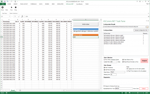
Version 3.11.2.0
518 downloads
ASComm Excel Add-in is a simple to use, non-programmatic way to populate Excel 2007 - 2021 (version 16) spreadsheets with data from PLCs, instrumentation, and other process hardware. ASComm Excel Add-in uses built-in drivers for Allen-Bradley ControlLogix, CompactLogix, MicroLogix, Micro800, PLC5, and SLC500 communications. No OPC, DDE, external drivers, or programming required. -

[Demo Software] - Excel Add-in for Allen-Bradley Data Logging
Automated Solutions posted a topic in Download Comments
View File Excel Add-in for Allen-Bradley Data Logging ASComm Excel Add-in is a simple to use, non-programmatic way to populate Excel 2007 - 2016 spreadsheets with data from PLCs, instrumentation, and other process hardware. ASComm Excel Add-in uses built-in drivers for Allen-Bradley ControlLogix, CompactLogix, MicroLogix, Micro800, PLC5, and SLC500 communications. No OPC, DDE, external drivers, or programming required. Submitter Automated Solutions Submitted 03/01/16 Category Demo Software -

logix 5000 Upgrade to v20.01 from 17
bagged2drag posted a topic in Allen Bradley / Rockwell Automation
I a tried upgrading logix5000 from v17 to v20.1. While 5000 is launching, it shows at the bottom that versions up through 20.1 are installed, but once it is fully loaded and logix is up, when I go to the help- about, it only shows version 17 even if I choose the dropdown. Does anyone know if this is normal? Alternatively, would somebody have a file they could send me that is v20 so I can verify it works? When I did the update, most of the upgrade selections seemed to fail, but when I tried to reinstall, it said everything was already installed. Kris -
Hi: I know how to update the S7-1200 by this link: http://www.tecnoplc.com/actualizar-firmware-s7-1200-de-una-cpu-6es7-214-xxx-0xb0/ , but anyone knows about update the Firmware with other type of Memory Cards??? Is it available with 12MB or 4MB card??? Thank you a lot.
-
Multiple PLCs CIP Messaging Single CLX Main PLC
Stockman posted a topic in Allen Bradley / Rockwell Automation
I have a project that has moving carriers that each have their own CompactLogix processor onboard communicating over wireless to the main Controllogix PLC. When each station needs to update the supervisor or vice versa we enable a CIP Data Table Write to the other PLC. We have 36 moving stations basically, and one main. Looking for any tips from anyone who has had a similar project. We have lost messages in our trial and may need to sequence the messages. Thanks in advance. -
Hello, I hope you are all having a great Wednesday. So I was wondering if this is possible, and if so, how to do it. What I'm trying to do is get a real time speed of my hydraulic cylinder using a transducer, a 1769-HSC high speed counter module, and a 1769-L36ERM processor. Kind of like a speedometer in my car. I would like the number in inches/ second. We use a hydraulic proportional valve to control a cylinder that we use to pump molten lead into our die cast machines. Back in the day they used to use limit switched that rest on a tail rod attached to the cylinder shaft to get an approximate stroke length. It was very crude, but it worked for what it was. I'll explain a little more, in case I'm not explaining it very clearly. So on most of our machines the maximum stroke length of a normal shot is about 11". We have different "stages" to the shot. Stage one is typically from 0" (when the shot is all the way returned) until about 1.5", at 1.5" the valve stops and there is a shot delay for 1 second (vacuum draws some lead into the goose neck and into the beginning of the mold), after the delay second stage starts, second stage is from 1.5" to 4", third stage is from 4" to 8" and fourth stage is from 8" to 11.5" or until the shot timer finishes timing, and then another valve switches, and the shot starts it's return. We have the different stages because we typically shoot the cylinder slower at first, and then delay and then almost maximum velocity. We control the velocity with an analog output to a solenoid on a hydraulic valve. For example, for the first stage we may open it up 20%, then 0% during the delay and then 85% during second, third and fourth. Sometimes we play around with different shot delay times, different shot velocities, sometimes 3rd may be faster than 4th, ect, to get the best die casted parts. Anyways, so in the past they would use limit switches. One was a button head style that when the shot cylinder shaft was all the way returned, it made the switch, and we knew the shot was fully returned. One was set at 1.5", 4", 8" etc. They all, except for the shot return switch, were roller style limit switches. They were all made, and once the shot reached that stroke length, they would come off the rod and we would know we were in that next stage. So it was very crude. If you wanted to adjust the stages you would have to climb up on top of the very hot molten lead pot, mark where the limit switch currently was (in case you needed to put it back) loosen the bracket, try to make a measurement and guess how far you moved it. It was crude to say the least. Some of our older style machines that don't need much tweaking still use the limit switch style positioning system. Most of our new machines all use a VisiTrak transducer. The shot cylinder rod that is attached to the cylinder shaft is actually threaded and then has a very thing layer of chrome plating. The transducer sits against the shaft and counts the threads. It transfers those counts to a Very High Speed Counter module in our PLC I/O rack. We have a CompactLogix L36ERM processor and we use a 1769-HSC as the VHS Counter. Then we just do some math in the PLC program and we are able to get shot stroke in inches. We set different compare instructions, for example when: Shot_Stroke is greater than or equal to 0 AND Shot_Stroke is less than or equal to 1.5 then 1st_Stage_Bit is active. We set up different numbers for all the different stages and still use the button head limit switch as a second method to confirm that the stroke is fully returned. The counter is very fast. We are able to know what the shaft stroke is at any given point. We currently do some math using the distance of each stage and using timers to calculate inches per second of each stage. That way we can have a nice Speed number in inches/second that we can use to make different adjustments to the shot. Typically the first stage is about 7"/second second is: 24"/second third is: 42"/second and fourth is 2"/second. But I want a real-time, current speed, not just the speed that it traveled through each of the stages. Ok, after all of that explaining, I'm finally getting to my question. How would I logically write a set of instructions that could give me current speed in inches per second. Like i said, I am able to calculate the speed of each stage, after the shot has completed the stage, I just divide the distance of the stage (in inches) by the time it took to travel through that stage (in seconds). But I would like to have a real time speed, kind of like a speedometer on a car. Is this possible? I know that the scan time on this processor is very fast and the high speed counter module counts very fast as well. How do I do the math to get a real time speed in inches/ second? Sorry for the very long post. I just thought i would give you a background on what we are doing/ would like to do. Thank you very much.
-
Connecting a Fanuc R-30iB controller to CompactLogix L30ER
hboyer90 posted a topic in Allen Bradley / Rockwell Automation
Hello, I am trying to get a Fanuc R-30iB controller added into my RSLogix program. The PLC is a CompactLogix 1769-L30ER When I search for new modules to add I see a pre setup Fanuc Robot Ethernet module, but I can't get that to work. I tried following Fanuc's instructions and setting it up as a generic ethernet module, but I couldn't get that to work either, it just says i/o not responding for that module. I am definitely able to ping the Fanuc controller, so I believe I am seeing it. When I add the controller in RSLinx, it's there, but there is no icon next to it's name. I'm guessing because its a fairly new controller, and it came out after the version of RSLinx that I'm using? Don't I need to download the EDS file for the new controller so that Linx can recognize it? Any help would be greatly appreciated. Thanks -
Can a 1769-L36ERM communicate on 2 separate Ethernet networks?
smhiestand posted a topic in Allen Bradley / Rockwell Automation
Using its internal Ethernet ports, our 1769-L36ERM processor communicates with 15 other devices inside the same machine. Can a rack mounted Ethernet module be installed to allow communication to/from this processor and an external network containing a SCADA system and RSLogix 5000 workstations? We prefer not to add all 16 devices to our external network and our I/S department does not allow routing devices on the network that they did not install. -
compactlogix firmware upgrade fail
islam141414 posted a topic in Allen Bradley / Rockwell Automation
I have new compactlogix plc L43, it was 1.4 firmware rev and when i try to upgrade the firmware the communication lost during upgrade , I make this upgrade using Serial communication (very slowwwwww) Now i cannot see the plc on RSlinix and cannot communicate with it I know that if the communication loss during firmeare upgrade, the PLC will be stop and it should return back to allen bradley any one have soloution for this problem ?????????????? -
Help with HMIs (PanelView Plus Compact 400)
Evilbeard posted a topic in Allen Bradley / Rockwell Automation
Hi. I'm taking a class through my job (I'm an industrial maintenance technician), and they've offered us the schooling through our local community college. They bring the trainers and laptops to our site, and we have class there. We're in our "PLC II" class, and we're using CompactLogix 5332E 1769-L32E PLCs with PanelView Plus Compact 400 HMIs. I'm having issues with getting my PLC to work properly with the HMI. I have a very simple program. A pushbutton turns on a timer with blinks a light. I have my tags as Green_On and Output_Green. They're obviously aliases for Local:1:Data.0 and Local.2:O.Data.0. I created a screen in FactoryTalk View ME, and gave it two simple pushbuttons. One a Maintained and one a Momentary. I created tags in the HMI, and linked them to the tags in the PLC. I have the button properties set as such: I create the runtime application and send it to the HMI. When I push the buttons on the HMI, I get no response from the PLC. If I push the manual pushbutton on the trainer, the PLC reacts appropriately and the buttons on the HMI change state (from the tag indicator). What am I doing wrong? Obviously the HMI is seeing the PLC, because the pushbuttons are updating the to tags change in state from 0 to 1. Why is it when I press the buttons, I'm not writing the value to the tags and the PLC changing state? I've talked to the instructor, but he's been retired for some time, and while he's given us a good overview of the basics, he's a bit out of his depth. -
Hello. I searched for an answer for this but it is still not very clear to me. I have a new Guardlogix 1756-L72S. I would like to create a project to work with it with firmware version 20.13. I have RSlogix5000 v20.01(CPR 9 SR 5) which should be compatible with it (in fact I can open projects with another guardlogix that have that firmware version) BUT when I create my new porject, the firmware version RSLogix5000 puts is v20.11 1. How could I create a project with the firmware version 20.13 for my guardlogix? (Didn't find an AOP for this) 2. If I update the guardlogix to firmware 20.13 with the CONTROLFLASH, could I still be able to go online and work with it, even though my project has a different firmware version? Thanks!
-

CompactLogix using Analog Press Encoder
jrupp82 posted a topic in Allen Bradley / Rockwell Automation
I'll set the scene a little before I explain the issue that I am having. I have an application where I have a Linear Servo Slide acting as a Press Kick-off cylinder on a ceramic press. In order to trigger this Slide accurately, I have installed an Absolute Rotary Encoder (a Turck product) to the press, which outputs an Analog signal for its specific position. I then have this as an input into my CompactLogix L33ERM through a 1769-IF4 Analog Input card. Within my code, I'm trying to capture the moment where the press has presented the part out of the die and it can be ejected from the press cavity without damage the part. Mis-timing on this ejection and the part will clip the die pad tooling and incur damage upon ejection. Now, one last point of clarification, I am a Mechanical Engineer by trade, so I don't claim to be an expert programmer. But I have learned a lot and have gained experience in programming applications like this, so I can learn quick and should be able to program this task. I have had my local Allen Bradley guy look at the code I'm using for this application, and he thinks it looks good, but I'm still having issues. What I have done, is within the code, I have a window that I look for, of the encoder's position, to trigger the ejection shoe to fire its sequence and kick the part off. However, I have had to make this window so large in order for the code to see it every press cycle, that occasionally, the ejection shoe will be fired at the back end of the window, which is actually too late, and my part is being damaged. Attached is a snapshot of the code. The OkSamplePress.DN is actually a timer that I have that looks at the current press rate and puts a delay in to not allow the kick-off to fire too early, because I was actually getting a glitch before where the kick-off would fire prematurely for some reason. I don't know if anyone can offer assistance on this or not, but I would greatly appreciate any help at all. Its become quite frustrating, as the rest of my machine functions quite well, and this seems to be the nagging issue I can't get rid of. Thanks in advance...Josh -
Ugrade PV600 (RS-232 DH485), comm.to ML1500, to PV+
grey posted a topic in Allen Bradley / Rockwell Automation
Hello experts, There's an existing PanelView600 (2711-K6C5 which has only RS-232-DH485 communication port) communicating to a MicroLogix 1500 (it seem to be an LRP processor since the serial communication is connected on the CPU left side) via female-female 9pins ribbon cable (used all 9 wires that I tested just straight-connect). Now my questions: 1) I read that I can upload PV600 project direct to laptop w/serial port using also straight connect 9pins cable (using just pins 2,3 and 5) and 1747 PIC/AIC+ driver on RSLinx. Could I just use the 9pin straight ribbon cable (using all 9pins) currently used by the PV comm. to ML1500 (unplug port to ML1500 then plug to laptop serial)? 2) Could I also use this same cable to upload ML1500 program (unplug PV600 port then plug to laptop serial)? 3) The new PanelView Plus 600 is a 2711P-K7C4A8. Could this new one also used that old same ribbon straight cable? I checked that this PV+ basic RS-232 port could also handle DH485 protocol and I also checked on a manual named "Legacy PanelView to PanelView Plus 6 Catalog Number Conversion" that it seems it's the particularly the correct counterpart of the old PV600, which also particularly emphasize the comm. port (RS-232-DH485). That's exactly what this is supposed to mean right, namely that the 2 panels have similar communication port, hence no need to modify anything on communication (esp. hardware/cable) right? I'm worrying because the plant guys said that those previous conversion, the other guys wasn't able to use the same ribbon 9pins straight cable from ML1500 side port to new PV+, instead they had to use the round port of the ML1500 and then used cable with some converters along the way before reaching the PV+. What do you think? Any inputs would really be appreciated! -
Download mode bit in RSLogix5000 CompactLogix?
hboyer90 posted a topic in Allen Bradley / Rockwell Automation
Hey, this may be an obvious question, but here goes: I have a CompactLogix L36ERM running RL5000 controlling one of our lead die cast machines. When I make a change to the program offline and need to download I always go and shut the machine down for safety reasons before downloading. One of our techs stopped the machine but left the control power and hydraulic pump on while downloading (something we are not supposed to do) when he finished downloading he switched it back to run mode and the machine closed on it's own and started right back up. This is a safety concern to me. We have a "close enable" tag that is true when all necessary conditions are met, and gets latched on when the machine is running in full auto. Before he downloaded the machine was at idle, meaning that the only way to close the machine would be to press the two dead-man switches to start the process. But, when he downloaded it started up automatically. Now I know the reason why is when the program was last saved, the "close enable" tag had a value of 1, it was latched on, so it bypassed the dead-man switches. A quick fix would be to save the program with that tag un-latched so that it can't start up on it's own after downloading. But, in case somebody saves the program while the machine is running and with that tag latched on, I need a better solution. Is there any tag or bit that goes true when a program is downloaded or when the mode of the PLC is switched from run to download to run? I want to manipulate that tag so that when I download it un-latches the "close enable" tag. I'm sure there is a way to do it, I'm just not even really sure what to search for in the online help. Any help is greatly appreciated. Thanks Howard -
MicroLogix 1100 to CompactLogix L-45 via MSG command
PaulKim1003 posted a topic in Allen Bradley / Rockwell Automation
Hello, I am trying to communicate with MicroLogix 1100 from CompactLogix. But I keep getting an error and It says connection failure. This is what I have done so far. Can anyone tell me what I am missing? Regards, -
Hey guys, so I feel like I must be doing something wrong here, well obviously since I cant get it to work. So I have a CompactLogix L36ERM running RSLogix5000, I've got 28 cards in total, all working except for one. My 1769-OF8V Analog Ouptut module. I just want to be able to output a 0-10v signal to a proportional valve module, specifically a Parker PCD00. Anyways, so I am online with the processor, everything is looking good, I/O is responding. I have the specific channel on that output module enabled in the module properties. I have tried changing the data type to every different option, I have raised and lowered the limits. I think I am addressing it correctly. I am just trying to move a value into that channel's data file. It appears to be moving the number in just fine, but when I put a meter on the output for that channel, I get 0V from the output to analog com. There is a little switch inside the module that allows you to use rack power or external 24V, I tried switching it down and using an external 24VDC source, I currently have it switched up to use the rack power. I'm lost. If somebody could please help me out and tell me if there is something obvious that I'm missing or doing wrong/ take me through an easy step by step way of setting this up for basic 0-10v output, that would be great. Sorry for being so new, I have attached a couple screenshots of the logic I'm using and the way I have it configured right now, but I have tried all different configurations. Thanks, Howard
-
Creating a HTML based HMI: Read/Write values to PLC
tpoirier posted a topic in Allen Bradley / Rockwell Automation
Hi all, So this is more of a theory / how would you attack this problem, question: I'm creating my first HMI and while playing around in FactoryTalk View Studio I noticed I can add objects to a screen. I can add a browser and with some work I can get it to display an HMTL file directly in the screen. So the browser in this case is opening a file stored locally, not something served up from the internet. Which opens up the question, could I write most of my HMI in HTML and Javascript? As a previous developer having the ability to control more of the UI would be amazing and perhaps easier to use/maintain. The only pitfall that I haven't been able to figure out is how to get real time values from the PLC. I'd welcome anyone's input on the idea in general or if someone knows a good method for getting/setting values from the PLC. Thanks! -
Hello all, I am experiencing an unusual (and what appears to be an unheard of) behavior in my CompactLogix L18ER controller. I am setting the date/time of the controller from my work station, however when I GSV WallClockTime, it is reporting 4 hours different. I have asked our local resources as well as done some forum and knowledgebase searching without result. Has anyone encountered this before? Attached is a screenshot of the controller time vs. the wall clock time. This isn't mission critical since it can be manually adjusted however I would like to understand what is taking place that would cause this behavior. Thanks!
-
S7 to CompactLogix through Prosoft PLX32-EIP-SIE
bgtorque posted a topic in Allen Bradley / Rockwell Automation
Hi I have a customer who wants to communicate some setpoint information from their Siemens S7 PLC to a CompactLogix L32E PLC. I have installed a Prosoft PLX32-EIP-SIE for ethernet-to-Siemens Industrial Ethernet comms. On receiving a setpoint in from the S7 I then close a loop with some speed feedback in the L32E with a PID. I don't have any access to a Siemens S7 (or software) to test that the comms is working before the unit is shipped, all I have is the CompactLogix hardware. I do have a second CompactLogix PLC / PanelView HMI, but I dont think that this will give me the comms to talk to the SIE port in the Prosoft. I was hoping to have a simple slider on the PanelView to change an integer value to simulate the setpoints coming from the S7. Does anyone have any idea how I might implement this with AB hardware / RSLogix / FactoryTalk? -
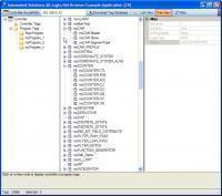
Allen-Bradley Logix Family Tag Browser Library for .NET Framework 2.0 - 4.8. ASBrowse.NET
Automated Solutions posted a file in Demo Software
Version 1.1.5
1451 downloads
ASBrowse.NET for Allen-Bradley Logix family is a class library for program and tag browsing on A-B Logix family of controllers. View and download any Allen-Bradley Logix Family controller's tag database without RSLogix 5000 or Studio 5000. Can be purchased as ready-to-run application, or as a .NET class library allowing you to incorporate tag browsing into your own applications. Potential uses Quick and easy browsing and verification of programs and tags outside of programming software Runtime tag selection in conjunction with other Automated Solutions products such as ASComm.NET communications driver. Runtime tag selection in conjunction with third party applications or drivers. Bulk edits for importing back into PLC/PAC programming software Documentation Key Benefits Allows you to browse programs and tags on A-B ControlLogix family without the need for RSLogix 5000 Does not require RSLinx or 3rd party drivers Supports controller tags and program tags Supports UDTs and PDTs 100% managed code x86, x64, and Any CPU compatible Visual Studio.NET 2022, 2019, 2017, 2015, 2013, 2012, 2010 (Express, Pro, Premium, and Ultimate Editions) Runtime-free for qualified applications -
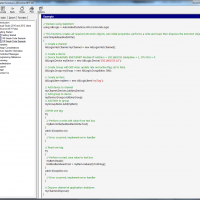
Allen-Bradley Ethernet Driver Library for .NET Framework (2.0 - 4.8) - ASComm.NET
Automated Solutions posted a file in Demo Software
Version 3.11.5.0
2804 downloads
.NET class library for use in Visual Studio.NET to create HMI/SCADA apps that communicate with A-B ControlLogix, CompactLogix, Micro800 Series, PLC5, SLC500, and MicroLogix PLCs via Ethernet. For .NET Framework 2.0 - 4.8 projects. Does not require OPC, RSLinx, or 3rd party drivers. x86, x64, and Any CPU compatible. Visual Studio.NET 2010, 2012, 2013, 2015, 2017, 2019, and 2022 compatible Supports unsolicited messages. Most .NET Framework targets are supported, including Web, Windows, console, and service apps. Can be configured programmatically or visually Visually design your entire communications configuration without writing a single line of code Extremely high performance - 5~10 mSec typical transaction time Supports ControlLogix family native tag names Supports reading and writing entire ControlLogix family UDTs and PDTs Supports block transfers of up to 250 words per transaction Tag database can be configured via code or visual designer Abstract base classes allow you to write generic code that works with all drivers Synchronous and asynchronous read/write methods Data change notifications Provides common user interface across all driver classes No limit on number of devices or data points Multi-threaded for high data throughput Includes extensive help system Example applications with VB and C# source code included. Easily connect office systems to factory floor. Runtime-free for qualified applications


