Search the Community
Showing results for tags 'compactlogix 1769-l32e'.
Found 88 results
-
Hello, I was hoping for some help in trying to read/write to a handful of bits in a CJ1M-CPU13 controller from a Compact GuardLogix. The CJ1M rack has a CJ1W-ETN21 card that is already communicating to a handful of Yaskawa drives. Is it possible for me to communicate with this controller from a CLX unit over ethernet? I don't believe an ETN21 card uses EIP but is there a way around this? Right now, I'm struggling to even find the IP address of the ETN21 card as the CX-Programmer file provided to me by the customer does not have the card in the IO configuration and I've never worked with Omron PLCs before. I found a CJ2M to CLX guide but it assumes communication over Ethernet IP and the ethernet port is native to the controller. Any help at all would be appreciated. Thanks!
-

Etherhet problem compactlogix 1769-L32E
mabauti posted a topic in Allen Bradley / Rockwell Automation
Hi everybody: I'm writing here because I have an Etherhet problem with my compactlogix 1769-L32E. I connect a crossover cable between my pC and the controller, then I run the BOOTDHCP server program . The BOOT DHCP window only shows the MAC of the PC, the controller´s MAC doesn't show even if i wait for more than 10 minutes I hope you can´t hel -
Best Practices (Standard Operating Procedures) CompactLogix & PanelView
craisondigital posted a topic in Allen Bradley / Rockwell Automation
We've purchased an Autoclave at auction with CompactLogix L32e and PanelView Plus 1000. With the help of some forum members and a local engineering company we have the machine finally working! I'm looking for some advise as to how to train users for standerd operation. For example: Their is a toggle switch on the front which powers on everything (PanelView, processer, switch, etc). We close at 5pm each night.. Should we Power down the machine each night, or leave it on? Another user mentioned a battery and I was a bit confused with the manual. With the machine off, Is the PLC only holding the program because of the battery?? I have backups of the following.. (.acd, .apa, .mer) files. I also have created a Disc Image of the Internal Flash card on the PanelView. Is their anything else I should have a backup of? Their is a CF card in the PLC. It has a folder called "Logix" and one called "System Volume Information" In the Logix folder is a CurrentApp folder with a .bin and .p5k file. Does anyone know what exactly these are doing?? Any other advise is greatly appreciated. Thanks so much for your time. -
How to connect micro 850 with compactlogix 1769-L24ER in Studio 5000
necrofear1885 posted a topic in Allen Bradley / Rockwell Automation
Good morning i want to know how i can recognize into the compactlogix 1769-L24 ER the micro 850 (2080-LC50-24QBB), because i want to communicate this two devices with MSG, i already i can see these two equipments into RSlinx but when i start Studio 5000 i don't know whick module i have to use it to recognize the micro 850, please help me -
Hi Everybody, I would like to get the Connections from an AB CompactLogix L32 with CIP. I can see these connections on the web interface. According to the CIP Vol1 v3.3 documentation I have created a reqest in java which requests the first instace of the Connection Manager Object with Get_Connection_Data service. I captured the sent and the received packets with wireshark. I would like to ask the following: 1.) Is this the correct way to request the connections from the PLC with CIP? 2.) The response says that "Service not supported", is it possible that the PLC does not support this service or there is problem with the request? 3.) Is there any other way to get the connections (I/O and Message) from the PLC with a CIP reqest? Thanks for the answers in advance.
-
Run time free production .NET AB Logix library
Mandeep Ahuja posted a topic in Allen Bradley / Rockwell Automation
Hello guys, Newbie on this site. I am looking for a run time free Allen Bradley .NET driver. Basically a library (.dll) that implements communication protocols to Allen Bradley PLC's ( CIP, Ethernet/IP, etc.). Can someone point me in the right direction please ?. -
I have just started programming PLC's and the first thing I have came up against is a 4-20ma signal to a analog card for a Turbidity meter. The problem I am having is the reading is very erratic. Is there any way to get it from jumping around so much?
-
I have just started programming PLC's and the first thing I have came up against is a 4-20ma signal to a analog card for a Turbidity meter. The problem I am having is the reading is very erratic. Is there any way to get it from jumping around so much?
-
Hello Im new using HMI got1000, Im trying to connect using Ethernet this HMI to a compactlogix, i already imported the tags, but i can't use any of them, because the gtworks3 says "you have to map the tags for set a device", i dont know what means map the tags, some one can help me please?
-
I was practicing some concepts on concurrency in periodic tasks where I handle such using SSV instruction to inhibit tasks, as suggested by Logix5000 Programmer Manual and after I downloaded the program through ethernet cable to the PLC (Compact Logix L32E) it became impossible to communicate to it, showing 1789 Virtual Chassis in the Who Active Window isntead of the PLC I'm using. I tried to reconfigure it using RSLinx and serial cable but I had no success, the only solution was reset it by removing its batery. I was wondering what could have caused the problem. Concurrency.ACD
-
CompactLogix L24: Do I need an external ethernet module to talk to an ethernet device?
lifejustice posted a topic in Allen Bradley / Rockwell Automation
I have a compactLogix L24. It is connected to a network switch. I also have an ethernet servo driver (KM AKD) attached to the same switch. The CL L24 IP address is 192.168.150.1 The Servo Driver is 192.168.150.3 In RSLogix 5000, I added an ethernet module. I put in the IP address for the servo driver. When I go online, I just get a connection error (Code16#0204). I can talk to the servo driver using my PC on the same network (192.168.150.13), but the CompactLogix won't talk to it. Do I need to install an external ethernet module to make this work, or can I use the existing ethernet ports on the L24? I'm stumped. -
Processor or Program Name Tag RSLogix 5000
hboyer90 posted a topic in Allen Bradley / Rockwell Automation
Hey guys, this is probably a stupid question so I apologize if it is, but I have a PanelView Plus 6 700 and a CompactLogix L36ERM on one of my machines at my plant. We have several different molds that run in this machine, so we have 5-7 different PLC programs that can possibly run in this processor, depending on which mold is in. I'm planning to go to a single program with recipes, but I haven't had the time to set that up yet. So we use the PanelView for troubleshooting, and adjusting process paramters. On the main screen in the PanelView I have the time/date and also the program name. What I have been doing is just creating a string tag in RSLogix 5000 that is the program/processor name (we use the same name for the processor and program) and then on my PanelView I just create a string display that looks at the string tag name in the processor. That way anytime a mold is changed over and the PLC program is downloaded, the PanelView displays the correct program/processor name. Now this is all fine and dandy and works as long as if a new program is created, we remember to change the string tag to the name of the new program, we often run new sample parts and what we do is rename an existing program that has similar logic and save it as a new program name. The problem comes up because if somebody copies an existing program and makes a new one, the string tag is still going to say the name of the old PLC program. Now if we only had one or two or even 5 machines, it would be simple enough to just remember to change that string tag. Our, or I should say MY problem is that we have approximately 40ish machines in our plant, and I can't always remember to change that string tag every time we create a new program. I should say that I have been, but there are times that I may forget. My question is this, is there any way that in FactoryTalk View ME Studio to have a string display the name of the processor or the name of the PLC program automatically without having to manually enter the name into the string tag that I created in RSLogix 5000? Like is there a system tag somewhere that has the name of the processor or the name of the program? That was way more explaining then probably necessary. It's early and I've had way too much coffee haha. Thanks guys. -
All, I have a 1769-L24ER-QBFC1B processor with a 1769-ASCII card that I am trying to get working on the bench. I have a standard serial cable hooked up from Channel 0 of the ASCII card to the COM1 port of my computer. All I'm trying to do at this point is a simple bare-bones hello world program with a terminal (termite or putty) so that I can verify my setup and understand how it works before I try to implement it on the plant floor. I have the card set up in alternating mode and am using the pre-canned program found starting on page 35 of the user manual(1769-um012) .This is my first time using the ASCII card I am familiar with the CompactLogix processors and the RSLogix Suite. Any insight you can give would be greatly appreciated. Thanks, Lucas
-
From what I can tell, there is no built-in PLC simulator within RS Logix 5000, and I have to download a separate package that requires another licence to be paid for? Is that really the case??
-
How do I add a constant string to a CompactLogix PLC and RSLogix5000? How do I copy one string to another? I have found links to using the COP instruction, which is fair enough, but the source parameter needs a tag and not a literal. How do I get a value into the tag? Can I really only do it when online? I'm new to Allen Bradley, and finding string usage to be very confusing so far.
-
PAROCK1 for HMI/SCADA View File Now a software solution is available for your Modbus (MB) needs in Rockwell/Allen-Bradley Control Logix or Compact Logix (Clgx) family processors, instead of a traditional 3rd party hardware like Prosoft MVI-56, Molex SST-SR4-CLX-RLL etc. It is an Add-on instruction (AOI) for PLC/PAC firmware v16 or later, (other solutions are available for pre v16 systems). For hardware interface, use PLC’s channel 0 (serial) or TCP/IP Interface module(s) to have as many MB TCP/IP devices or serial devices. (Some limits apply based on system configurations, Comm. settings depending on HW used.) Connect any MB Client/Master or Server/Slave device(s) to your CLgx PLC, including flow computers, analyzers, VFDs, Power Monitors, Level gauges, Smart I/O, etc. All the MB public/native function codes are supported. 32-Bit integers/floats as single entity are supported with byte and word level swapping. A separate utility automates the data mapping to your PLC logic. Features -Serial Master (BASIC required Option); TCP; Slave; Redundancy; More than 5000 accumulative registers; MB CFC (Custom/Private Function Code) Support; Data mapping too – Between PAROCK1 & your PLC logic; Packaged with Rockwell; TCP/IP Interface Module; Volume Discounts; Annual Support Requirements -Rockwell/AB-CLgx processor with v16 or later. Contact PCI for earlier versions. -If using CPU’s Chan0, you cannot use Chan0 for any other user mode activity. You can use it for non-user mode activities -TCP/IP Interface Modules from Rockwell/AB supported, are: -1756-EN2xx ControlLogix® Ethernet/IP communication modules, firmware revision 5.007 or later -1756-EWEB ControlLogix Ethernet/IP web server module, firmware revision 4.006 or later -1768-EWEB CompactLogix Ethernet/IP web server module, firmware revision 1.002 or later -1769-L30ER, 1769-L30ERM, 1769-L30ER-NSE, 1769-L33ER, 1769-L33ERM, and 1769-L36ERM CompactLogix controllers, firmware revision 20.011 or later -1769-L24ER-QB1B, 1769-L24ER-QBFC1B, 1769-L27ERM-QBFC1B CompactLogix controllers, firmware revision 20.011 or later -1769-L16ER, 1769-L18ER, 1769-L18ERM CompactLogix controllers, firmware revision 20.011 or later Other Related Services/Items -Custom PLC Add-on instructions building -PLC upgrades, troubleshooting, applications -PC Windows, iOS5, Linux, Mobile devices Comm. Drivers -Custom development, Technology Transfer Services -Other Non-AB communication drivers for serial or TCP -Full control system integration, training, architecture design This driver can be conviniently used with Visual Studio in development of complete large scale complex HMI/SCADA Systems. It can be used to perform advanced reporting MES, analytics, IoT, Big data type apps. One example is available to download here For More Info Overview of Parijat Drivers: Click here Additional supporting Info about Parijat Drivers:Click here Complete Related Driver options: Click here Submitter Scadadoctor Submitted 03/10/16 Category Other PLC Demo Software
-
Version 3.11.2.0
518 downloads
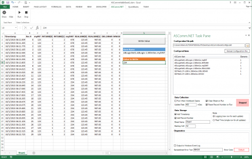
ASComm Excel Add-in is a simple to use, non-programmatic way to populate Excel 2007 - 2021 (version 16) spreadsheets with data from PLCs, instrumentation, and other process hardware. ASComm Excel Add-in uses built-in drivers for Allen-Bradley ControlLogix, CompactLogix, MicroLogix, Micro800, PLC5, and SLC500 communications. No OPC, DDE, external drivers, or programming required. -

[Demo Software] - Excel Add-in for Allen-Bradley Data Logging
Automated Solutions posted a topic in Download Comments
View File Excel Add-in for Allen-Bradley Data Logging ASComm Excel Add-in is a simple to use, non-programmatic way to populate Excel 2007 - 2016 spreadsheets with data from PLCs, instrumentation, and other process hardware. ASComm Excel Add-in uses built-in drivers for Allen-Bradley ControlLogix, CompactLogix, MicroLogix, Micro800, PLC5, and SLC500 communications. No OPC, DDE, external drivers, or programming required. Submitter Automated Solutions Submitted 03/01/16 Category Demo Software -
Multiple PLCs CIP Messaging Single CLX Main PLC
Stockman posted a topic in Allen Bradley / Rockwell Automation
I have a project that has moving carriers that each have their own CompactLogix processor onboard communicating over wireless to the main Controllogix PLC. When each station needs to update the supervisor or vice versa we enable a CIP Data Table Write to the other PLC. We have 36 moving stations basically, and one main. Looking for any tips from anyone who has had a similar project. We have lost messages in our trial and may need to sequence the messages. Thanks in advance. -
AB analog input card response time too slow compactlogic
leescott posted a topic in Allen Bradley / Rockwell Automation
First post. We recently upgraded our machine from an SLC to compactlogix. In the SLC 5/05 we used analog 1746-ni8 cards for pressure and position sensors. When we moved over to the compactlogix 1769 l36erm with 1769-if16c cards we seen issues where the analog values had very little definition accuracy. This can be resolved by changing the filters but then the response time of the card is to slow and we miss data. All of the relevant code from these sensors are in their own task and ive tried periodic, event and continous tasks but none of this helps. The strange thing is with the SLC we never seen these issues. Any ideas how i can improve the reponse time when the filters are set low? -
Hello, I hope you are all having a great Wednesday. So I was wondering if this is possible, and if so, how to do it. What I'm trying to do is get a real time speed of my hydraulic cylinder using a transducer, a 1769-HSC high speed counter module, and a 1769-L36ERM processor. Kind of like a speedometer in my car. I would like the number in inches/ second. We use a hydraulic proportional valve to control a cylinder that we use to pump molten lead into our die cast machines. Back in the day they used to use limit switched that rest on a tail rod attached to the cylinder shaft to get an approximate stroke length. It was very crude, but it worked for what it was. I'll explain a little more, in case I'm not explaining it very clearly. So on most of our machines the maximum stroke length of a normal shot is about 11". We have different "stages" to the shot. Stage one is typically from 0" (when the shot is all the way returned) until about 1.5", at 1.5" the valve stops and there is a shot delay for 1 second (vacuum draws some lead into the goose neck and into the beginning of the mold), after the delay second stage starts, second stage is from 1.5" to 4", third stage is from 4" to 8" and fourth stage is from 8" to 11.5" or until the shot timer finishes timing, and then another valve switches, and the shot starts it's return. We have the different stages because we typically shoot the cylinder slower at first, and then delay and then almost maximum velocity. We control the velocity with an analog output to a solenoid on a hydraulic valve. For example, for the first stage we may open it up 20%, then 0% during the delay and then 85% during second, third and fourth. Sometimes we play around with different shot delay times, different shot velocities, sometimes 3rd may be faster than 4th, ect, to get the best die casted parts. Anyways, so in the past they would use limit switches. One was a button head style that when the shot cylinder shaft was all the way returned, it made the switch, and we knew the shot was fully returned. One was set at 1.5", 4", 8" etc. They all, except for the shot return switch, were roller style limit switches. They were all made, and once the shot reached that stroke length, they would come off the rod and we would know we were in that next stage. So it was very crude. If you wanted to adjust the stages you would have to climb up on top of the very hot molten lead pot, mark where the limit switch currently was (in case you needed to put it back) loosen the bracket, try to make a measurement and guess how far you moved it. It was crude to say the least. Some of our older style machines that don't need much tweaking still use the limit switch style positioning system. Most of our new machines all use a VisiTrak transducer. The shot cylinder rod that is attached to the cylinder shaft is actually threaded and then has a very thing layer of chrome plating. The transducer sits against the shaft and counts the threads. It transfers those counts to a Very High Speed Counter module in our PLC I/O rack. We have a CompactLogix L36ERM processor and we use a 1769-HSC as the VHS Counter. Then we just do some math in the PLC program and we are able to get shot stroke in inches. We set different compare instructions, for example when: Shot_Stroke is greater than or equal to 0 AND Shot_Stroke is less than or equal to 1.5 then 1st_Stage_Bit is active. We set up different numbers for all the different stages and still use the button head limit switch as a second method to confirm that the stroke is fully returned. The counter is very fast. We are able to know what the shaft stroke is at any given point. We currently do some math using the distance of each stage and using timers to calculate inches per second of each stage. That way we can have a nice Speed number in inches/second that we can use to make different adjustments to the shot. Typically the first stage is about 7"/second second is: 24"/second third is: 42"/second and fourth is 2"/second. But I want a real-time, current speed, not just the speed that it traveled through each of the stages. Ok, after all of that explaining, I'm finally getting to my question. How would I logically write a set of instructions that could give me current speed in inches per second. Like i said, I am able to calculate the speed of each stage, after the shot has completed the stage, I just divide the distance of the stage (in inches) by the time it took to travel through that stage (in seconds). But I would like to have a real time speed, kind of like a speedometer on a car. Is this possible? I know that the scan time on this processor is very fast and the high speed counter module counts very fast as well. How do I do the math to get a real time speed in inches/ second? Sorry for the very long post. I just thought i would give you a background on what we are doing/ would like to do. Thank you very much.
-
Connecting a Fanuc R-30iB controller to CompactLogix L30ER
hboyer90 posted a topic in Allen Bradley / Rockwell Automation
Hello, I am trying to get a Fanuc R-30iB controller added into my RSLogix program. The PLC is a CompactLogix 1769-L30ER When I search for new modules to add I see a pre setup Fanuc Robot Ethernet module, but I can't get that to work. I tried following Fanuc's instructions and setting it up as a generic ethernet module, but I couldn't get that to work either, it just says i/o not responding for that module. I am definitely able to ping the Fanuc controller, so I believe I am seeing it. When I add the controller in RSLinx, it's there, but there is no icon next to it's name. I'm guessing because its a fairly new controller, and it came out after the version of RSLinx that I'm using? Don't I need to download the EDS file for the new controller so that Linx can recognize it? Any help would be greatly appreciated. Thanks -
Can a 1769-L36ERM communicate on 2 separate Ethernet networks?
smhiestand posted a topic in Allen Bradley / Rockwell Automation
Using its internal Ethernet ports, our 1769-L36ERM processor communicates with 15 other devices inside the same machine. Can a rack mounted Ethernet module be installed to allow communication to/from this processor and an external network containing a SCADA system and RSLogix 5000 workstations? We prefer not to add all 16 devices to our external network and our I/S department does not allow routing devices on the network that they did not install. -
compactlogix firmware upgrade fail
islam141414 posted a topic in Allen Bradley / Rockwell Automation
I have new compactlogix plc L43, it was 1.4 firmware rev and when i try to upgrade the firmware the communication lost during upgrade , I make this upgrade using Serial communication (very slowwwwww) Now i cannot see the plc on RSlinix and cannot communicate with it I know that if the communication loss during firmeare upgrade, the PLC will be stop and it should return back to allen bradley any one have soloution for this problem ?????????????? -
Help with HMIs (PanelView Plus Compact 400)
Evilbeard posted a topic in Allen Bradley / Rockwell Automation
Hi. I'm taking a class through my job (I'm an industrial maintenance technician), and they've offered us the schooling through our local community college. They bring the trainers and laptops to our site, and we have class there. We're in our "PLC II" class, and we're using CompactLogix 5332E 1769-L32E PLCs with PanelView Plus Compact 400 HMIs. I'm having issues with getting my PLC to work properly with the HMI. I have a very simple program. A pushbutton turns on a timer with blinks a light. I have my tags as Green_On and Output_Green. They're obviously aliases for Local:1:Data.0 and Local.2:O.Data.0. I created a screen in FactoryTalk View ME, and gave it two simple pushbuttons. One a Maintained and one a Momentary. I created tags in the HMI, and linked them to the tags in the PLC. I have the button properties set as such: I create the runtime application and send it to the HMI. When I push the buttons on the HMI, I get no response from the PLC. If I push the manual pushbutton on the trainer, the PLC reacts appropriately and the buttons on the HMI change state (from the tag indicator). What am I doing wrong? Obviously the HMI is seeing the PLC, because the pushbuttons are updating the to tags change in state from 0 to 1. Why is it when I press the buttons, I'm not writing the value to the tags and the PLC changing state? I've talked to the instructor, but he's been retired for some time, and while he's given us a good overview of the basics, he's a bit out of his depth.