Search the Community
Showing results for tags 'cam control data'.
Found 201 results
-
Which type of electrical panel is most reliable, give some idea about that ..?
-
Hi, I am using syswin and i am doing an exercise on saving and moving data. My challenge is am monitoring temperature from a sensor and the range is -20'C to 100'C from the 4-20mA sensor, after conversion and testing for positive and negative the values are stored in D205. (I have done the conversion and testing for positive and negative values only assigning of bit 15 in D205 is left) The simple program has to turn on Bit 15 if the value is supposed to be negative. 1000 0000 0000 0001, a simple approach to telling us this is -1’C. 0000 0000 0000 0001, is telling us this is 1’C. Bit 15 is going to be our Sign Flag, so we have to ensure that if the temperature is positive then Bit 15 = 0, how can we do this make Bit 15 of D205 = 0? If the temperature is negative then Bit 15 = 1, how can we do this make Bit 15 of D205 = 1? How can i turn on this bit inside a data word? for negative i thought i could just add #8000 to the values after conversion then storing in D205 but for positive values how do i ensure that bit 15 is 0? How could you approach this? Am a bit stuck, all thoughts and ideas are much appreciated if possible you could add a snapshot from syswin or cx-programmer. I have attached the WTANK.SWP file which can be opened in syswin or cx-programmer. Look in block Main 8 Temp Buffer, Network 3 Convert to 'C WTANK.SWP
-
I just need to understand a little bit more about the PCS7 architecture, if someone could point me to a document or a video or something, or just give me a few sentences to break it down it would be greatly appreciated. The reason being, we have a quote that we are working on for a customer over seas and are being told to quote our equipment with an S7-410 PLC. I am very unfamiliar with Siemens in general, but completely unfamiliar with the PCS7. Our equipment is typically if not almost always stand alone equipment that communicates discretely to the rest of the facility. Our equipment is not part of a process line, but rather feeds the process line equipment what it needs to perform its operation. I have been led to believe that the S7-410 PLC must be part of a DCS, so it does not seem like the correct fit for our equipment. I just want to confirm this and learn a little bit more so I can explain to our sales folks and ultimately the end user why it is the wrong option for us and our type of equipment. Thank you!!! Heather
-
Hi Everyone, I have a PowerFlex 525, in Velocity Mode with a Encoder Card "25-ENC-1". We are controlling this drive via TCP/IP with a 1769-L32. Through the PLC if I try to toggle the Bit for "Pos Redefine" in A560 [Enh Control Word] it instantly turns back to 0. But through the Parameter List Editor I am able to toggle A560. For My function I need to have the drive in Velocity Mode, If I change the drive to Position Mode I am able to toggle "Pos Redefine" Any Thoughts would be great
-
Hi guys, been using this site for a long time, it has come in handy alot. However I have recently taken on my first servo project, heres an overview of the project We have a filling machine that has a separate dosing system to the filler head. It used to keep the dosing in time by adjusting a 0-10v signal to an inverter to make sure that a flag makes a sensor in a set window. I have installed an encoder on the filling head and an mpl servo to the dosing. I have then used an MAPC instruction to follow the encoder, the cam is 0-360 and it follows a straight linear line. I have installed of this as a temporary set up on one of the filling machines (we have 2) and it is working perfectly. I have now installed this on the second machine as a permanent set up with a panelview plus 7, L71 cpu. However it is giving a very strange problem on first power up, the encoder is giving the exact same position as before it was powered down. however as soon as the MAPC executes the servo axis faults, giving an overspeed fault. the servo doesnt even look like its attempting to move (however it is through a 10-1 gearbox). if i then home the encoder it then runs absolutely perfectly until it is powered down again. I am beginning to think it may be to do with the master lock and cam lock position, as the cycle stop position of the two machines are different. however I just cant seem to get my head around i the difference between them. Hopefully that makes sense any help would be greatly appreciated Thanks Rhys c1_dosing.ACD
-
Which type of software is used for data matching in excel sheet.
-
Hi, Is there any setup to manage alarms in one PLC from multiple CX-Supervisor runtimes running on different computers? If I get an alarm, it shows up on both runtimes. If I acknowledge from one runtime, I also want it to be gone from the list in the other runtimes.
-
 I have an application I am currently working on where I have a single AB ControlLogix PLC that needs to read data from 12+ Omron CJ2M PLCs. The Omron PLCs don't need to read any data from the AB. I have tried several things including the generic .eds file from Omron and the instructions in the document I found on this site: Omron CJ2 to Rockwell ControlLogix Ethernet/IP Datalink. The generic .eds file gave me a D6 error on the Omron side and after talking to support it does not seem like the correct path. When I tried following the instructions for the datalink I ran into several issues. The first issue was that after configuring my network in the Omron software upon trying to load it I got a unit mismatch message for the 1756-EN2T, the .eds file I have is for a 1765-EN2T but the card shows as a 1756-EN2T/D, so I am concerned that could cause an issue...that being said I can't find any .eds file specifically for the /D revision. The next thing I noticed was that there doesn't seem to be be a way to link the produced data from the Omron to the AB, the Omron configuration software with the AB .eds files loaded only gave me the option to send data to the Omron which we do not need to do. I created a generic Ethernet module in my RSLogix program for the Omron PLC and then created a consumed tag and linked that to the module but I do not see where I set up the link on the Omron side for that, so how does it know what addresses to read?? Any help would be greatly appreciated!!!! Thank you!
 -

Problem when showing website using HMI (Microsoft Web Browser Control)
GooGoo posted a topic in HMI & SCADA
Hi All. i got a problem when accessing local reporting service website using microsoft web browser control at HMI. it showing only half of page. when i open the website from internet explorer at same server where i develope HMI, i got no issue. please your advice. thank you. -
I am new to ifix, I am having an issue, I am unable to receive any information, after attempting to fix the fact that the view was only pulling half the data I lost it all, I had a back up saved, but it didn't work on restoring communication, I was getting a cannot connect to node error, but I have fixed that, now all I am getting is question marks. essentially I believe that I have two standalone computers with the ifix software and the communicate directly with various plcs that share information across, either a ring topology or full connected. so the computer I have that is working is setup with scada and the database and MB1 with no network support, the one that is not working is set up the same, my cable connection is a usb to Ethernet and im communicating with a Comm port on the computer. I've tried different comm ports, even contacted GE, they were suppose to have someone call me back but no one has yet. Can anyone give me an idea of what I've got wrong here?
-
Version 1.0.0
131 downloads
Logic takes two inputs (I0.0, I0.1), debounces each (T0, T1), looks for actuation during a timed period (T2), and provides validation (M20.0). This logic is not designed, nor intended, to replace the use of any OSHA required two-hand safety control relay. It is provided for the sole purpose of it's educational value. -
FC1 Two hand anti tie down View File Logic takes two inputs (I0.0, I0.1), debounces each (T0, T1), looks for actuation during a timed period (T2), and provides validation (M20.0). This logic is not designed, nor intended, to replace the use of any OSHA required two-hand safety control relay. It is provided for the sole purpose of it's educational value. Submitter pop29684 Submitted 03/22/16 Category PLC Sample Code
-
I need to learn about position control for 2 axis with a QD75MH2 module. I know how the basics about programming with the Q Series PLC but I've never done any positioning control. I'm having a really hard time understanding the program I have to modify and I don't know where to start. Is there any course you might recommend? Even if I have to pay for it. Thanks.
-
I am doing a data collection from OMRON PLC CP1L through MS excel VBA use API function. The connection was setuped correct (I think)both in PLC and PC side. The trick things is when PLC have USB cable connected the data was send to PLC and can get feedback through RS232 in normal.(I use portmon moniter the progress,and I can see the data (C-command ).But when I get the USB cable removed ,The PLC can not get any reponse back.Dose any of you have met that before?
-
PAROCK1 for HMI/SCADA View File Now a software solution is available for your Modbus (MB) needs in Rockwell/Allen-Bradley Control Logix or Compact Logix (Clgx) family processors, instead of a traditional 3rd party hardware like Prosoft MVI-56, Molex SST-SR4-CLX-RLL etc. It is an Add-on instruction (AOI) for PLC/PAC firmware v16 or later, (other solutions are available for pre v16 systems). For hardware interface, use PLC’s channel 0 (serial) or TCP/IP Interface module(s) to have as many MB TCP/IP devices or serial devices. (Some limits apply based on system configurations, Comm. settings depending on HW used.) Connect any MB Client/Master or Server/Slave device(s) to your CLgx PLC, including flow computers, analyzers, VFDs, Power Monitors, Level gauges, Smart I/O, etc. All the MB public/native function codes are supported. 32-Bit integers/floats as single entity are supported with byte and word level swapping. A separate utility automates the data mapping to your PLC logic. Features -Serial Master (BASIC required Option); TCP; Slave; Redundancy; More than 5000 accumulative registers; MB CFC (Custom/Private Function Code) Support; Data mapping too – Between PAROCK1 & your PLC logic; Packaged with Rockwell; TCP/IP Interface Module; Volume Discounts; Annual Support Requirements -Rockwell/AB-CLgx processor with v16 or later. Contact PCI for earlier versions. -If using CPU’s Chan0, you cannot use Chan0 for any other user mode activity. You can use it for non-user mode activities -TCP/IP Interface Modules from Rockwell/AB supported, are: -1756-EN2xx ControlLogix® Ethernet/IP communication modules, firmware revision 5.007 or later -1756-EWEB ControlLogix Ethernet/IP web server module, firmware revision 4.006 or later -1768-EWEB CompactLogix Ethernet/IP web server module, firmware revision 1.002 or later -1769-L30ER, 1769-L30ERM, 1769-L30ER-NSE, 1769-L33ER, 1769-L33ERM, and 1769-L36ERM CompactLogix controllers, firmware revision 20.011 or later -1769-L24ER-QB1B, 1769-L24ER-QBFC1B, 1769-L27ERM-QBFC1B CompactLogix controllers, firmware revision 20.011 or later -1769-L16ER, 1769-L18ER, 1769-L18ERM CompactLogix controllers, firmware revision 20.011 or later Other Related Services/Items -Custom PLC Add-on instructions building -PLC upgrades, troubleshooting, applications -PC Windows, iOS5, Linux, Mobile devices Comm. Drivers -Custom development, Technology Transfer Services -Other Non-AB communication drivers for serial or TCP -Full control system integration, training, architecture design This driver can be conviniently used with Visual Studio in development of complete large scale complex HMI/SCADA Systems. It can be used to perform advanced reporting MES, analytics, IoT, Big data type apps. One example is available to download here For More Info Overview of Parijat Drivers: Click here Additional supporting Info about Parijat Drivers:Click here Complete Related Driver options: Click here Submitter Scadadoctor Submitted 03/10/16 Category Other PLC Demo Software
-
C200HW-MC402.pdf View File C200HW-MC402-E Motion Control Unit Operation Manual Produced June 2001 Submitter IO_Rack Submitted 03/09/16 Category Manuals
-
-

Version 3.11.2.0
422 downloads
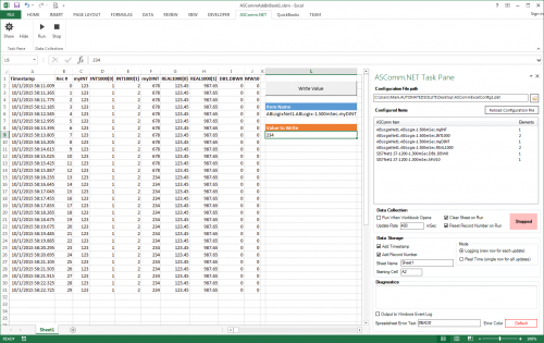
ASComm Excel Add-in is a simple to use, non-programmatic way to populate Excel 2007 - 2021 (version 16) spreadsheets with data from PLCs, instrumentation, and other process hardware. ASComm Excel Add-in uses built-in drivers for Modbus/TCP and Modbus RTU/ASCII communications. No OPC, DDE, external drivers, or programming required -

[Demo Software] - Excel Add-in for Modbus/TCP Data Logging
Automated Solutions posted a topic in Download Comments
View File Excel Add-in for Modbus/TCP Data Logging 3.6.8 ASComm Excel Add-in is a simple to use, non-programmatic way to populate Excel 2007 - 2016 spreadsheets with data from PLCs, instrumentation, and other process hardware. ASComm Excel Add-in uses built-in drivers for Modbus/TCP and Modbus RTU/ASCII communications. No OPC, DDE, external drivers, or programming required Submitter Automated Solutions Submitted 03/01/16 Category Demo Software -
Version 3.11.2.0
84 downloads
ASComm Excel Add-in is a simple to use, non-programmatic way to populate Excel 2007 - 2021 spreadsheets with data from PLCs, instrumentation, and other process hardware. ASComm Excel Add-in uses built-in drivers for GE / Emerson PACSystems (RXi, RX3i, RX7i), Series 90 (90-30), and VersaMax communications. No OPC, DDE, external drivers, or programming required. -

Version 3.11.2.0
518 downloads
ASComm Excel Add-in is a simple to use, non-programmatic way to populate Excel 2007 - 2021 (version 16) spreadsheets with data from PLCs, instrumentation, and other process hardware. ASComm Excel Add-in uses built-in drivers for Allen-Bradley ControlLogix, CompactLogix, MicroLogix, Micro800, PLC5, and SLC500 communications. No OPC, DDE, external drivers, or programming required. -
[Demo Software] - Excel Add-in for Allen-Bradley Data Logging
Automated Solutions posted a topic in Download Comments
View File Excel Add-in for Allen-Bradley Data Logging ASComm Excel Add-in is a simple to use, non-programmatic way to populate Excel 2007 - 2016 spreadsheets with data from PLCs, instrumentation, and other process hardware. ASComm Excel Add-in uses built-in drivers for Allen-Bradley ControlLogix, CompactLogix, MicroLogix, Micro800, PLC5, and SLC500 communications. No OPC, DDE, external drivers, or programming required. Submitter Automated Solutions Submitted 03/01/16 Category Demo Software -
I have restored a crashed IFIX to a new PC. The restore is ok and installed GE9 driver. With the GE9 power tools, we can observed that data transmits and recieve. The problem is that the screen scada is not updating i.e. no status/feedback, anything is happening. The LAN network TCP/IP was configured i.e. IP, subnet and gateway. Any remedies/advice is most welcome. Please provide a guide on the communication/configuration setup. Thanks
-
Wanting to learn computer programming/data collections for industrial applications
Matt47715 posted a topic in Computer Help and Networking
Hi, I work as an industrial programmer primarily dealing with Allen Bradley, Mitsubishi, and Omron PLC's as well as various peripheral devices. I would like to begin the process of learning computer programming as it pertains to the manufacturing industry. I'd like to learn how to write databases (SQL, etc) and VB apps and eventually I'd like to be able to write applications that can communicate with PLC's and other devices (although the last one would be a ways down the road). I have very little experience with computer programming so I don't really know where to start. What language should I learn first? What free software is available to learn with? What resources do you recommend I use? I've downloaded Visual Basic Express and found some introductory courses online that I've just started but if there is something else I should've started with I'm open to suggestions. Thanks -
Hey guys, first post! Friends at Practical Machinist sent me over here b/c we were stumped. I have a Mitsubishi 500M control CNC machine. There is a section of the ladders that i don't understand, and Mitsubishi couldn't help, and the OEM is defunct. I do not have a hardcopy of the ladder circuits. I have an output , [Y13], that i can't get to turn on because of an internal relay | M453 | see pic 1 When i searched for relay M453, it seems as if it's in some sort of array function. see pic 2 None of the relays from M448 thru M512 ever turn on. I understand that all these are controlled thru this circuit, but i have no clue what is going on with the R registers, and how the heck these internal relays can be turned on. Can you guys help explain? Thanks!