
Search the Community
Showing results for tags 'arduino'.
Found 7 results
-
Hi all, I'm not shure if I saw it once, a Spanish site with a rugged I/O shield for an arduino plus a software package to build an Arduino-PLC packet. It was pretty much $$$ raised... (on my oppinion, for my application, not to dispretiate their value). Has anyone thought of it or knows of such an ensemble: A general Arduino board, a general kind of "plc-shield" (some inputs, some outputs,...) and finally, a (preferably open-source) software package to make an off-the-shelf Arduino-PLC ish? Maybe it all exists with some name changes, or this question is of a huge ammount of ignorance. Thanks. Corvo (means Raven)
-

ModBus RTU communication between Omron CP1E (CP1W-CIF11) and an Arduino using MAX485 RS485 transceiver
José Silva posted a topic in CX-Programmer
Hello everyone! Briefly introduction, I would like to communicate and test the following hardwares: 1- Omron CP1E (using an Option Port CP1W-CIF11) ; and 2- Arduino Nano using MAX485 RS485 transceiver. The CP1E will operate in "Modbus-RTU simple master" as illustrated in image 01. The arduino will be in slave mode address 1 and the library used is "SimpleModbus NG" ( https://github.com/angeloc/simplemodbusng/tree/master/SimpleModbusSlave ). Taking the sample in official manual ( https://industrial.omron.eu/en/services-support/technical-tools/downloads#cp1e ) , pages 248-253 in the "CP1E CPU Unit Software User's Manual" (Image 04) describes a sample communication to an "Inverter Slave". I want to use the Arduino Slave as the Inverter Slave just to be sure that all previous steps are correct. Therefore, I would like to know: 1- As illustrated in Image 02, Am I missing any resistors? 2- Should I connect the GND to the FG? 3- In this scenario, the DIP switch setup should be as illustrated in image 03? Only DIP4 is OFF. 4- Can I test it just forcing A641.00 and checking the DM Area Data, as shown in Image 05? The code used in it is the following: // Wiring: Arduino and MAX485 // RX0 - RO // TX1 - DI // D2 - DE/RE #include "SimpleModbusSlave.h" enum { REGISTER_0, REGISTER_1, REGISTER_2, REGISTER_3, REGISTER_4, REGISTER_5, REGISTER_6, REGISTER_7, REGISTER_8, TOTAL_REGS_SIZE }; unsigned int holdingRegs[TOTAL_REGS_SIZE] = { 0, 1, 2, 3, 4, 5, 6, 7, 8 }; void setup() { modbus_configure(&Serial, 9600, SERIAL_8N1, 1, 2, TOTAL_REGS_SIZE, holdingRegs); } void loop() { modbus_update(); } Any answer can be helpful. Thank you for your time! Regards, Jose. -
Im trying to use my PT100 with an Arduino-based PLC from Industrial Shields, which is basically an Arduino Mega encased in a plastic container. Im using a 250Ω resistor, actually 237Ω resistor between Analog and Ground. Here is my setup: Here is my code: int sensorValue = 0; int temperature = 0; int ReceivedByte = 0; float f1 = 0; float t1 = 0; void setup() { Serial.begin(9600); Serial.println("hi..."); } void loop() { delay(1000); sensorValue = analogRead(A2); Serial.println(sensorValue); temperature=map(sensorValue,639,719,0,110); f1 = temperature; // Float conversion Serial.print(f1); Serial.print("\n"); } These are my results for room temperature: I got the values from an online pt100 table for resistance and tabulated them from 0-110C in 10 deg increments and for the corresponding resistance using: nADC = 1023 * ( 237Ω/(237Ω+Rpt100)) Its not working because im getting values of ~300 for room temp which is well below this range, but since its not constrained (the map function). What should I do? Thanks
-
Can we interface the arduino sensors like HC-SR04 an ultrasonic sensor that gives a PWM as output.Can it be read on PLC by any means ? How we can read the Discrete values of Ultrasnonic sensor on PLC ? any one who knows Kindly guide I'm working on Fatek PLC FBs 24 MAR-AC
-
Dear friends, I'm a Ph.D. student at the University of Alabama in Huntsville, and my research topic is SCADA cyber security. My goal is to find vulnerabilities in PLCs and try to fix them. However, its really hard to study something deep when you don't have the source code. Therefore, due to the lack of open source tools available in this field, I decided to create my own open source PLC. Then I realized that this could be useful for other researchers and professionals in the field, so I'm here sharing it with everyone. The OpenPLC is a complete package with an editor and a compiler. The editor runs in Windows, Linux and MacOS and supports all the 5 IEC 61131-3 languages: ST, IL, LADDER, FBD and SFC. The compiler is responsible for getting the program written by the user and compile it to the platform in which the OpenPLC is running. The OpenPLC currently runs on Raspberry Pi, Arduino, UniPi and also as a soft-PLC on Windows or Linux. If you guys have any of the mentioned boards laying down somewhere, it might be interesting to give the OpenPLC a try. More information can be found at the project's website: www.openplcproject.com Let me know if you have any comments. Thanks, Thiago Alves
-

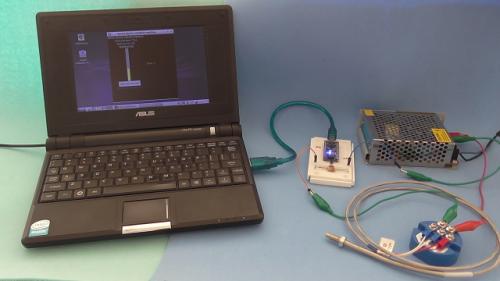
Temperature measurement using Arduino Nano, RTD PT100 temperature sensor and 4-20 mA transmitter
Absolutelyautomation posted a file in Other PLC Demo Software
Version 1.0.0
130 downloads
Temperature measurement usind Arduino Nano, RTD PT100 sensor, 4-20 mA current loop transmiter, and a python app for visualization -
[Other PLC Demo Software] - Temperature measurement using Arduino Nano, RTD PT100 temperature sensor and 4-20 mA transmitter
Absolutelyautomation posted a topic in Download Comments
View File Temperature measurement using Arduino Nano, RTD PT100 temperature sensor and 4-20 mA transmitter Temperature measurement usind Arduino Nano, RTD PT100 sensor, 4-20 mA current loop transmiter, and a python app for visualization Submitter Absolutelyautomation Submitted 04/01/16 Category Other PLC Demo Software