Search the Community
Showing results for tags 'MC S Class Compact Motion Con'.
Found 79 results
-
Hi Guys! I have a problem with Motion axis move (MAM) command. There is an Allen bradley servo motor what is working well. But I need to add a new program section, wich is in a specified moment, the axis should move a certain distance. I think I need to use the mam command, just I dont know how can I configure the motion control part. I need to make a new tag ? or what ? I need to use a user define ? PLS help me.
-
Version V12 (2017)
43 downloads
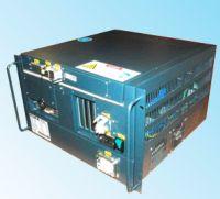
KUKA, Optional Interfaces for KRC4 Compact controller such as I/O, fast measure interface etc. -

[Robots and Servos] - KRC4 Compact Optional Interfaces
panic mode posted a topic in Download Comments
View File KRC4 Compact Optional Interfaces KUKA, Optional Interfaces for KRC4 Compact controller such as I/O, fast measure interface etc. Submitter panic mode Submitted 03/02/18 Category Robots and Servos -
HOW TO CONNECT AB 1769-L33ER ETHERNET /IP TO MOD BUS RTU
-
Looking for some servo application help. Software: I have GX works 2, GT Designer, and GX Developer. Hardware: PLC L06CPU-P, GOT2000 HMI, MR-J4-350B servo amps, HG-JR35JK motors, LD77MS2 Pulser I have (2) AC servos that will simply move an aluminum frame backwards and forwards using a FESTO belt mover and I have a servo gear reducer 20:1. I have a "simple motion module"and all of this hardware and software, plenty of time, and would really like to finish this project off. But this is my first servo and my first hmi project. I have some experience with Omron, Mitsubishi, and Allen-Bradley plc's, and consider myself novice at best. Any sample programs or help getting me started would be greatly appreciated!
-
Hi Here's a question I'm about to ask Omron.. as soon as I can figure out who to ask.. It's complicated asking support.. their web email form doesn't make complex questions easy. Here's the question: Can the NJ CPU program a LinMot linear motor to make the "Random Sea"? The NJ has a mixed protocol.. Ethernet/IP and EtherCAT (CoE), and claims to be a "Motion Controller". I doubt Motion Control is available on it's Ethernet/IP line.. but the EtherCAT might be another story. Certainly The Omron NJ is a Motion Controller for Omron NJ series drives.. However, how well does it work with LinMot? Here's the curve. Imagine a LinMot Linear motor continuously moving, never really stopping, following a real-time, mathematically generated curve, moving positive then negative, at random frequencies and random amplitudes. Almost never repeating a motion sequence. looks something like this: Yet, after a while the motion history fully represents the spectral distribution of energy on the surface of the ocean. Spectrum analyzers can display it, and mathematics can define it.. I just have to make that sea in a model scale… (Time scales by the square root of the scale factor) And keep the water in the tank: https://www.youtube.com/watch?v=SQd6YzBWVvI The big question is: Can the Omron NJ get a LinMot Linear Motor to do this? … LinMot thinks YES.. but, isn’t sure. Yes there are ways to “connect" LinMot to The NJ.. EtherCAT (CoE), Ethernert/IP but… there is nothing in the LinMot drive that can create or store a predesigned Random Sea .. Only a Motion Controller, generating real time motion commands, by running mathematical equations, "on the fly” can do that. If the NJ is a true “Motion Controller”, and the LinMot C1250-DS-XC is implemented as an “axis” by Symac Studio, which it is… Then, there may be hope. Closed loop, PID feedback remains with the LinMot drive, with special settings in LinMot Talk … Homing might have to be done with the NJ .. or by Digital I/O’s What do the Omron experts out there think? Can this be done? Thanks much, Regards, Michael
-

Allen Bradley 5069 Compatlogix communication issue with Red Lion HMI
addie1309 posted a topic in Allen Bradley / Rockwell Automation
Has anybody tried communicating Allen Bradley 5069 Compact logix PLC with Red Lion HMI ? I am unable to communicate them in spite of adding AB tags via L5K file which gives me no error. I am able to see all the tags in Crimsion 3.0 software in development mode. However, PLC & HMI are not communicating with each other. I am able to ping to both, using the same program in PLC of which I generated L5K file. I think it may have something to do with the driver as 5069 is a new line of PLC Rockwell come out with only in 2016. -
Panel View 1000 and CompactLogix L32E cannot load the program
craisondigital posted a topic in Allen Bradley / Rockwell Automation
Thanks for your time. We have purchased from auction a Getinge Autoclave (sterilizer) with Allen-Bradley controls (CompactLogix L32E). The machine has a PanelView Plus 1000 installed. A CD came with the machine w/ the following files.. HMI Project - (.apa file) Runtime (.mer file) Their is also a compact flash card installed in the CompactLogix L32E. On the Panel View, their is an external Compact Flash slot, but no card, and on the inside of the panel view (if i remove the back cover) their is a compact flash card slot with a card installed. I haven't checked what is on either of those cards yet.. We cannot get the program to load on the panel view. When the machine is powered on, the panel view goes through a quick dos setup screen and then the screen turns blue and we are stuck with an hour glass icon. The icon will move depending upon where you touch on the screen. I can boot the panel view in safe mode (by hitting the default button, then reset) at which point I get a message stating that the machines files may be corrupted and leaves me the options to Download new Firmware, or Continue. Hitting Continue nothing happens, and choosing Download gives me Ethernet, or Serial options. The Panel View is connected to the PLC via ethernet so I choose this option and it gets stuck at this point. We do not want to make any changes to the program, but just to get it to run on the machine. We do not have ANY of the software. Any advise is greatly appreciated. Craig -
I want to run MR J3 A type 10 nos servo without using network, I'm to run servo using hardwired.please name motion controller to run 10 servo on hardwired..
-
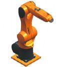
Version BA KR AGILUS sixx V10
18 downloads
KUKA: Agilus six axis -
KUKA: Agilus View File KUKA: Agilus six axis Submitter panic mode Submitted 02/16/17 Category Robots and Servos
-

A simple tutorial .smc2 project program for motion control (1) G5 servo
lamboom posted a topic in NJ Series / Sysmac Studio
hI.. I've asked for this in the past and, so far, haven't been very lucky. Most of the projects I run into have 4 or 5 axis, lots of analog and sensor input.. or don't have the HMI part of the "Machine" I have a nice NJ 101-1000 with the NA 7 inch HMI.. along with a R88BD-KNA5L-ECT servo and a 50W G5 motor.. type R88M-K05030H-S2. All On a nice rack with power supplies and some EtherCAT I/O (It all functions .. even "MC Test Run" gets the motor to jog .. But.. no way to "home" it.... The motor is in "rotary mode" but... it's NOT got an Absolute encoder.. it's a incremental... sniff! I just want it to stop on zero ..Or anywhere, and call it zero ... and make moves plus an' minus in degrees, that's all.... I assume I have to send it some signal (push button) while it's spinning that tells it it's in "Proximity" to home and it then it does something which makes it end up on zero. I've homed a lot of linear motors (LinMot) an' they are very easy to work with. But, Omron has 10 different homing modes .. and they aren't very well explained. Well, they aren't explained at all in that 502 page user manual... you have to already know how to do it, in order to understand the explanation... Example: Take the "Home Proximity Input Signal" .. I can imagine what it might do, to help control a move to home. I can even imagine what's making the signal .. and that somewhere there is a place where the homing parameters are set... like the "axis setting table" .. but, it's not a Global Variable, or a Data Type .. I could imagine it gets into the system from the CN1 I/O connector? or some I/O somewhere? But.. I grow weary of imagining how this system actually works.. Building a simple working project, from a tutorial, or even downloading a simple working project (.smc2 file) and making the minor adjustments to fit my equipment ... would make all the difference in the world. I've searched Omron's Libraries of .smc2 files. Haven't found any yet that aren't on the level of "Top Gun" (a seriously complicated project for a 1-week training class) ... Oh there are several.. related to IAG object files .. but those Library files are not "working projects" intended to serve as a Tutorial.. they are limited projects, ready to be configured with IAG Object files, and "your" programming ... So that you can write the programs you need "faster"... which is nice... but, no help here. Somewhere out there.. is a nice simple .smc2 project file where you get to control a simple motor from the HMI ..Preferably using an NJ CPU and a NA HMI .. home the motor.. jog the motor and input a few "go-to" positions... sigh!.. Like you would do in a One or Two Day class... This kind of thing should be already be available in the Sysmac Library ... Thanks much for listening.. sorry about the rant. -
I am trying to learn the logic of a process at my new job. There are tag names that I can't make sense of because they end with _xva, _xvb, _xvu, _xvd, _xvo, _xvc, _zsm, _zsu, _zsc, _zso, _zsd and so on and so forth. I know they are associated with motion, but I need to make better sense of them. There are no descriptors. What do they mean and is there a resource available that I can reference?
-
i need a example code for position control of MR-J3-20A with QD75D4 as intelligence module. and i want to see the parameter if possible
-
Just wondering if I need to set up two Motion Groups to specify the direction of travel along 1 AXIS? (Forward and Reverse) If not, how do I specify direction when using motion instructions (specifically MAM) with incremental motion.
-

Unable to load non compact machine edition application
Robert Alan Andersen posted a topic in Allen Bradley / Rockwell Automation
I get this error even if the application is compact edition. Plz halp -
Hello, I'm new to this forum and PLC world in general (especially to Mistubishi PLCs). I have a task in which I need to synchronize servomotor with another motor that runs conveyer (servomotor needs to stamp a label on a foil on a conveyer), in GX Works3. Servo motor is run by Simple Motion module. I need general tips on how to make pulses from encoder into something useful that can be used to send data to Simple Motion module. I need high speed counter to count pulses (never actually did this, I got this from manuals), how would I, for example, get speed out of it? Number n pulses, divide it with time it took to get to n pulses? How would I make Simple Motion to make servomotor on his Axis #1 to rotate at same speed?
-
Disable BOOTP on built in ethernet port
GeraldTech posted a topic in Allen Bradley / Rockwell Automation
It's another BOOTP post! I know you're all as excited as I am, so lets get started. But seriously, I'm trying to disable BOOTP on the built in Ethernet ports, not on an Ethernet module. I specifically say disable because BOOTP successfully assigns the IP address to my Compact Logix, however I still need to disable BOOTP to make it a static IP address rather than a dynamic IP address. I'm going to list everything that I have tried, so that anyone with the same issue can have an all-in-one-place reference. (Because there's a number of forum posts and other information for this topic on the internet, with many different suggestions) If I see different ideas/suggestions in other places, I can edit them into this post. Things I have tried: (and you should try if you have this issue) Disabling all firewalls, (For me: Windows/Avast) Disabling all other network adaptors. (Wifi especially, but any and all adaptors you are not using for the setup) Using a different laptop/operating system: (My current laptop runs windows 8.1 and uses a Linksys usb to Ethernet device to talk to the PLC, I tried a laptop running windows 7 which communicated using a built in Ethernet port) Lastly: Try to use all available methods to disable it. For me, that would be: BOOTP standalone server, RSLinx, (Trying to use both USB and Ethernet connections) and finally RSLogix. (Actually, only Ethernet modules have a "disable BOOTP" checkbox built into RSLogix, so that is not an option for me.) [If you have an Ethernet module, go to port configuration in RSLogix and uncheck the "enable BOOTP" checkbox] Anyway, RSLinx Classic (version 3.71) and BOOTP Standalone server (version 2.32) are each coming back with an error when I try to disable BOOTP. I'll attach a .jpg of some screenshots, and some Wireshark save files to show what I mean. In the RSLinx Wireshark file, it shows a "privilege violation" packet being sent from the PLC to the laptop towards the end of the exchange, but I'm not sure what privileges the laptop needs/doesn't have. For the wireshark files: I cleared everything happening before I try to send the command, so that there isn't a ton to search through. As far as timing of the wireshark files go: I start recording traffic, send the disable command (by clicking the disable BOOTP/DHCP button on BOOTP server or "apply" on RSLinx) then I stop recording traffic once I get the error message. So, the captured packets should be just the attempt to disable BOOTP and that's about it. I am sorry that I the pictures are strung together using paint, but I don't have photoshop on my work computer so it's the best I have. Any suggestions/help would be appreciated! (Regardless of whether they are suggestions for me, or suggestions that I may have missed intended for anyone with this problem.) Thank you for your time. Edit: I had the attached pictures open in paint/photo viewer, sorry that they look bad in the forum picture viewer. BOOTP_wireshark.pcapng rs_linx_USB_wireshark.pcapng rs_linx_wireshark.pcapng -
Hi guys, been using this site for a long time, it has come in handy alot. However I have recently taken on my first servo project, heres an overview of the project We have a filling machine that has a separate dosing system to the filler head. It used to keep the dosing in time by adjusting a 0-10v signal to an inverter to make sure that a flag makes a sensor in a set window. I have installed an encoder on the filling head and an mpl servo to the dosing. I have then used an MAPC instruction to follow the encoder, the cam is 0-360 and it follows a straight linear line. I have installed of this as a temporary set up on one of the filling machines (we have 2) and it is working perfectly. I have now installed this on the second machine as a permanent set up with a panelview plus 7, L71 cpu. However it is giving a very strange problem on first power up, the encoder is giving the exact same position as before it was powered down. however as soon as the MAPC executes the servo axis faults, giving an overspeed fault. the servo doesnt even look like its attempting to move (however it is through a 10-1 gearbox). if i then home the encoder it then runs absolutely perfectly until it is powered down again. I am beginning to think it may be to do with the master lock and cam lock position, as the cycle stop position of the two machines are different. however I just cant seem to get my head around i the difference between them. Hopefully that makes sense any help would be greatly appreciated Thanks Rhys c1_dosing.ACD
-
PAROCK1 for HMI/SCADA View File Now a software solution is available for your Modbus (MB) needs in Rockwell/Allen-Bradley Control Logix or Compact Logix (Clgx) family processors, instead of a traditional 3rd party hardware like Prosoft MVI-56, Molex SST-SR4-CLX-RLL etc. It is an Add-on instruction (AOI) for PLC/PAC firmware v16 or later, (other solutions are available for pre v16 systems). For hardware interface, use PLC’s channel 0 (serial) or TCP/IP Interface module(s) to have as many MB TCP/IP devices or serial devices. (Some limits apply based on system configurations, Comm. settings depending on HW used.) Connect any MB Client/Master or Server/Slave device(s) to your CLgx PLC, including flow computers, analyzers, VFDs, Power Monitors, Level gauges, Smart I/O, etc. All the MB public/native function codes are supported. 32-Bit integers/floats as single entity are supported with byte and word level swapping. A separate utility automates the data mapping to your PLC logic. Features -Serial Master (BASIC required Option); TCP; Slave; Redundancy; More than 5000 accumulative registers; MB CFC (Custom/Private Function Code) Support; Data mapping too – Between PAROCK1 & your PLC logic; Packaged with Rockwell; TCP/IP Interface Module; Volume Discounts; Annual Support Requirements -Rockwell/AB-CLgx processor with v16 or later. Contact PCI for earlier versions. -If using CPU’s Chan0, you cannot use Chan0 for any other user mode activity. You can use it for non-user mode activities -TCP/IP Interface Modules from Rockwell/AB supported, are: -1756-EN2xx ControlLogix® Ethernet/IP communication modules, firmware revision 5.007 or later -1756-EWEB ControlLogix Ethernet/IP web server module, firmware revision 4.006 or later -1768-EWEB CompactLogix Ethernet/IP web server module, firmware revision 1.002 or later -1769-L30ER, 1769-L30ERM, 1769-L30ER-NSE, 1769-L33ER, 1769-L33ERM, and 1769-L36ERM CompactLogix controllers, firmware revision 20.011 or later -1769-L24ER-QB1B, 1769-L24ER-QBFC1B, 1769-L27ERM-QBFC1B CompactLogix controllers, firmware revision 20.011 or later -1769-L16ER, 1769-L18ER, 1769-L18ERM CompactLogix controllers, firmware revision 20.011 or later Other Related Services/Items -Custom PLC Add-on instructions building -PLC upgrades, troubleshooting, applications -PC Windows, iOS5, Linux, Mobile devices Comm. Drivers -Custom development, Technology Transfer Services -Other Non-AB communication drivers for serial or TCP -Full control system integration, training, architecture design This driver can be conviniently used with Visual Studio in development of complete large scale complex HMI/SCADA Systems. It can be used to perform advanced reporting MES, analytics, IoT, Big data type apps. One example is available to download here For More Info Overview of Parijat Drivers: Click here Additional supporting Info about Parijat Drivers:Click here Complete Related Driver options: Click here Submitter Scadadoctor Submitted 03/10/16 Category Other PLC Demo Software
-
C200HW-MC402.pdf View File C200HW-MC402-E Motion Control Unit Operation Manual Produced June 2001 Submitter IO_Rack Submitted 03/09/16 Category Manuals
-
-
Hello All, I have a guardlogix processor that I just safety locked with a known password. When I tried to unlock, that password didn't work. Upon reading a bit I realized that the lock and unlock passwords are separate. I never set the unlock password but blank doesn't work. Could it be a leftover due to program copy paste or is there a way to find/reset this unlock password.
-
Dear colleagues and siemens experts, I''m new in siemens. As all I make my program for PLC, but I need help with PID autotunig (pretuning) I use : 1.CPU 1214C DC/DC/DC (6ES7214-1AG40-0XB0) 2. 6ES7214-1AG40-0XB02. 16IN/16 OUT DC/DC/DC (6ES7-223-1BL32-0XB0) 3. 2x 6ES7231-5PD32-0XB0 ( 4 channel RTD analog module - PT100) We use 7(seven) Pt100 points with 7(seven) heaters ... so I need 7 additional outputs..... [you can see example of wiring in attached pic 6es7231-5pd32-0xb0-modules.jpg] Maximum heating point is around 220 degrees. I make my configuration for PID_Compact : 1. Basic settings 1.1 Controller type : Temperature : °C Set mode to : Pretuning ( sometimes I make it Automatic mode) 1.2 Input_Per(analog) -----> Output_PWM 2.Process value setting: 2.1 Process value limits: Process value high limit : 220.0 °C 2.2 Process value limits: Default 3. Advance setting 3.1Process value monitor : Default 3.2 PWM limits Minimum ON time : 0.5 sec Minimum OFF time : 0.5 sec 3.3 Output value : Default 3.4 PID parameters : Default I start Commissioning with these steps : 1. Measurement : Sampling time 0.5 Start 2. Start PID_Compact 3.Tuning mode : Start When I try first time my setpoint was 90 degrees , second time I try with 120 degrees. After 4-5 hours it stop more in Progress bar it stop when I reach a little more then 50%, and I stop PID. For heaters it is not normal to process to be 4-5 hours, there have some wrong. Example with 120 degrees : During process I make : When Input_PER reach 120[1200] degrees I stop physical access to heaters. When Input_PER reach 100[1000] degrees I start physical access to heaters So 4-5 hours is soo long time for this type process. Time to reach 120 degrees from 100 degrees is around 2-3 min. Time to fall from 120 degrees to 100 degrees is around 4-5 min. Total time for one whole cycle around : 8min. Sometimes when I set setpoint to 140, 150 degrees it writes me that output set value is to high after I give Start Pretuning ? Even sometimes when try for 120 degrees .... As all I want to start PID pretuning (autotuning) with setpoint 140 - 150 degrees. Which are minimum requirement to start PID autotuning with PID_Compact ? Could you send me some very simple example and steps that I must make or only steps ? I attached files in dropbox with images and program example, because I can't attached nothing here. This form don't give me access to attached something. So link is here : Even program is there. Thanks in advance Best regards : Altan
-
Hello! I'm working on a project. I cannot get online with the PLC. The compagnie who made the program does not exist anymore so they cannot help me. Does anyone knows how to unlock a locked controller ? Do you know a compagnie who can solve this kind of problem ? Otherwise my only option is to wipe the all thing and reprogram it .... which would be bad. Thanks !