Search the Community
Showing results for tags 'INCOM IMPACC Modbus network'.
Found 292 results
-
HI, I'm reading values from an SBC SAIA PLC ( PCD2.M5540 model). My problem is that some values are 32 bit, while modbus return 16 bit values, of course. Registers are consecutive, so I cannot read for example 9008 and 9009 since they store 2 different information.To make it clearer I attach the PLC watch window. As you can see R9009 is a 32 bit value, but I can't require R9009 and R9010 via modbus since in R9010 register there is a different information. AS well as in R9008. Speaking with SAIA technical support, they explain me that their PLC registers are natively 32 bit, so in order to read them I need a 32bit modbus client. I cannot find anything like this, neither I can use standard modbus, since the buffer I get back is a 16 bit for each register. So 16bit for R9008, 16bit for R9009, 16 bit for R9010. What I can do?Thanks
-

How can I access an UR5 robot through Studio 5000?
Lucas Antonelo posted a topic in Allen Bradley / Rockwell Automation
Hello, everyone! I am following this YouTube tutorial where it teaches you how to add a block of Modbus server within Studio 5000 for communication with plc ControlLogix. The video: https://youtu.be/qcF4m7rPjkw However, according to a comment from the author of the video himself in my comment I can make such a connection through a Modbus device. How do I do this within ur5 and how can i access UR5 inside Studio 5000? -
Hi, I'm new to the Mitsubishi world, so may be anyone help me in a quick! I need to test a my client with the Mitsubishi MODBUS tcp. To do this I would like to avoid use a real plc and use the Gx Simulator3 that come with the Gx Works3. The question is: the Gx Simulator3 is capable to simulate a MODBUS tcp module? To be more specific I tried this: - created a project in Gx Works3 with a FX5U CPU. - configured the FX5U built-in ethernet module with IP address of the hosting pc (also tried 127.0.0.1 with no success). - activated and configured the MODBUS muster to the built-in ethernet module. - wrote a trivial ladder program with a 1 input and 1 coil. I can download and run the project on the Gx Simulator3 but I cannot connect to tcp port 502 that I supposed opened by the MODBUS muster functionality of the build-in ethernet module. Do anyone know if the Gx Simulator is able to simulate modbus tcp functionality? Thanks in Advance Luciano.
-
Hi guys I need to test some code in an FX5U PLC, but I don't have the PLC here so I'm trying to simulate it in melsoft gx works 3, but how I can test the Modbus tcp/ip if I do not have an IP address for the plc someone has ever communicate both software, gx works 3 an som modbus master software ??
-
Hello everybody. I need a solution for Modbus-TCP server on the PLC. With the FX3U it would work with the FX3U-ENET module. The internal interface of the FX5U should actually be able to work with the library of the FX3U (FX3GModbusTCPServer_GW2_V100) or not? Because a socket connection is now possible. I would be happy about suggestions. Dave
-
I am trying to change the subnet of this CP1L plc. Currently it is at 192.168.250.*** and I would like to change it to 192.168.54.***. I already tried starting fresh by writing to the controller with ip 0.0.0.0 and then putting my desired ip address after. When I try to write to the controller with a subnet other than .250 for example 192.168.54.13, the controller saves the node address(.13) but keeps the same .250 subnet which results in me being able to ping 192.168.250.13 successfully but get no response from pinging 192.168.54.13. Yes I did change my local network card when pinging different subnets and also did a network reset in CX-P after every ip change. Let me know if there is anything I am missing!!
-
Hi,I am running a Windows 10 VM with Rockwell Studio 5000 on a Windows 10 host PC. I communicate to the PLC network through a USB-C to ethernet adapter. Occasionally, the communications drop out, if this happens the only way I can re-establish comms, is to shutdown the VM and restore defaults in the virtual network editor, as this can happens a few times each day, it can be very frustrating.When this happens I cannot ping the host either, until the defaults are restored and the VM re-started.I am using the bridged connection in the VM.Can anyone help with this?Thank you
-
Hello, I'm new to setting up my controllers and communication between devices. We wanted to see if using Modbus TCP/IP to communicate to a load bank was the right path for us. I was able to configure my Micrologix 1400 controller Channel 1 for Modbus and set the data files. I set up a read holding register 03 message, two write single register 06 messages and one write multiple registers 16. I was able to read the data from the load bank, but I was unable to send any write commands. I didn't get any errors in the messages. I was able to send write commands through my pc to the load bank and it responded properly. So I was thinking I must of missed something in my set up in the PLC. I'm attaching the PLC Program and the command set from the manufacturer. Any help would be greatly appreciated. BENCH_TEST.RSS ALx Series Input Command.pdf ALx Series PWR Command Page.pdf ALx Series Setpoint Command.pdf
-
Currently have a A1SJ71E71-B2-S3 in the system for coaxial (thin) ethernet (10BASE-2), it's connected to a conversion module for TP-cable and from that then to a PC with plain TP network card. I was thinking about getting an A1SJ71E71N3-T to replace it and that way get rid of the converter from coax to TP. I wonder if it's possible to just have it hooked directly to the computer without hub - if I need a hub there's really no point in swapping - as there's still another thing between the computer and the PLC system that can cause problems. I was looking through the manual at mitsubiSIH.com and they seem to think they are connected to large nets with a bunch of hubs, PLC systems and computers. Appreciate thoughts and help.
-
Hi, First of all, thanks in advance for those who support and advises. I have a Modbus/TCP operational network as shown below. However, at any 1 time only 1 LAN is able to communicate instead of both LAN networks of the device. In another system with S.E Premium Unity PLC, both LAN networks are able to communicate at the same time. Thus, I would like to enquire if this is a limitation of Quantum NOE 771 whereby only 1 LAN can communicate at any one time or whether I have missed out any parameter/configuration settings? Any issue on the IP address configurations? Please advise. Thank you very much for the advise and assistance.
-
Hi all; I have Delta DOP110 IS hmi and i have a modbus tcp device. I want to communicate hmi and device with modbus tcp/ip but i didnt understand device's register address. For example, input bytes 0,1 analogue control word, What is the register address? 40.000 or 40.001 can you help me ?
-
Hello everyone, I have a problem, i want to read inverter holding register using modbus tcp. I am using QJ71MT91 and ABB580 FENA-21. QJ71MT91 successfully opened and no error was detected. I want to read the address to 101 and so on. in automatic communication parameter >> I have tried changing the target MODBUS Device Head from 0 to 102, and I got error code 7360. do I also have to use the auto refresh setting? I ask for guidance PLC Q03UDECPU : 192.168.3.181 PLC QJ71MT91 : 192.168.3.121 INVERTER : 192.168.3.11 i use gx works2 best regard chelz96
-

[Demo Software] - Modbus/TCP Client Driver Library for .NET 8.0, 7.0, 6.0, 5.0 & .NET Core 3.1 - ASComm IoT
Automated Solutions posted a topic in Download Comments
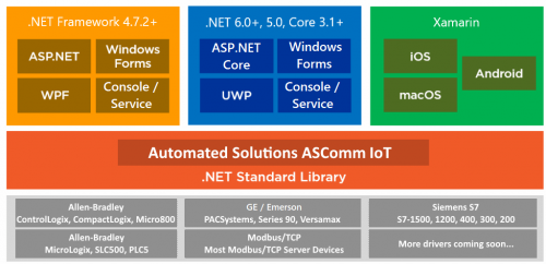
Modbus/TCP Client Driver for .NET 6, .NET 5 & .NET Core. - ASComm IoT View File ASComm IoT for .NET 6.0, .NET 5.0 & .NET Core developers. Class library for use in Visual Studio.NET to create HMI/SCADA apps that communicate with Modbus/TCP Server devices via Ethernet. Does not require OPC or 3rd party drivers Visual Studio.NET 2017, 2019 and 2022 compatible All .NET 6.0, .NET 5.0 & .NET Core targets are supported, including Web, Windows, console, and service apps. Runs on Windows, Linux & Android Extremely high performance - 5~10 mSec typical transaction time Supports Modbus functions 1, 2, 3, 4, 5, 6, 7, 11, 12, 15, 16, 17, 20, 21, and 24 Address mode support includes: Zero-based, One-based, Modicon 5-digit (1, 10001, 30001, 40001), Modicon 6-digit (1, 100001, 300001, 400001) Abstract base classes allow you to write generic code that works with all drivers Synchronous and asynchronous read/write methods Data change notifications Provides common user interface across all driver classes No limit on number of devices or data points Multi-threaded for high data throughput Includes extensive help system Example applications with VB and C# source code included. Easily connect office systems to factory floor. Runtime-free for qualified applications Submitter Automated Solutions Submitted 05/18/22 Category Demo Software -
Modbus/TCP Client Driver Library for .NET 8.0, 7.0, 6.0, 5.0 & .NET Core 3.1 - ASComm IoT
Automated Solutions posted a file in Demo Software
Version 1.4.1
34 downloads
ASComm IoT for .NET 8.0, 7.0, 6.0, 5.0 & .NET Core developers. Class library for use in Visual Studio.NET to create HMI/SCADA apps that communicate with Modbus/TCP Server devices via Ethernet. Does not require OPC or 3rd party drivers Visual Studio.NET 2017, 2019 and 2022 compatible All .NET 8.0, 7.0, 6.0, 5.0 & .NET Core 3.1+ targets are supported, including Web, Windows, console, and service apps. Runs on Windows, Linux & Android Extremely high performance - 5~10 mSec typical transaction time Supports Modbus functions 1, 2, 3, 4, 5, 6, 7, 11, 12, 15, 16, 17, 20, 21, and 24 Address mode support includes: Zero-based, One-based, Modicon 5-digit (1, 10001, 30001, 40001), Modicon 6-digit (1, 100001, 300001, 400001) Abstract base classes allow you to write generic code that works with all drivers Synchronous and asynchronous read/write methods Data change notifications Provides common user interface across all driver classes No limit on number of devices or data points Multi-threaded for high data throughput Includes extensive help system Example applications with VB and C# source code included. Easily connect office systems to factory floor. Runtime-free for qualified applications -
how read data from modbus read_var function
saruans posted a topic in Modicon / Telemecanique / Schneider Electric
hello, Somebody have suggest how need read data from slave using modbus RTU. I am using M241 PLC and read_var function. The picture you can see my PLC program. The data of slave is placed 3394 address. Then I try to read, always "READ_VAR" function get "CommError" which number is 254 that means "The detected operation error contains protocol- specific code" and "OpenError" which number is 3 that means I don't know. How need read from slave data, which modbuss adress is 3394? -
Here is a post that we recently completed on the Automation Direct USB to RS485 Adapter. The USB-485M is a 2-wire USB to RS-485 serial communication adapter for RS485 use. It does not require an external power supply or complicated configuration. It has a Type A (plug) USB connector for the computer side and a universal female RJ45/RJ12 modular connector. This will accept RJ12 and RJ45 plugs. The USB-485M supports multiple baud rates and is USB V2.0 Compliant. Read the rest of the post... YouTube Video on the installation and communication to a Solo Process Temperature Controller via Modbus RTU. https://www.youtube.com/watch?v=aWE05ZNZNXw Let me know what you think, Garry www.accautomation.ca
-
Hi there! I'm programming a CP1L-E CPU to control 3 3G3MX2 inverters via Modbus. It got some things right, like the INV002_Refresh_X31 block and its parameters. The thing is, I also want to read some parameters from the inverter using the INV206_ReadParameter block. My doubt is, do I need to be careful so both blocks don't execute at the same time and use the serial port at the same time? Is it better to use one INV206_ReadParameter block for each parameter I want to read? Thanks in advance!
-
I have this setup: FX3G CPU connected to GT2103 through RS422 (CH1). GT2103's ethernet port connected to LAN and set up as modbus TCP slave (CH2). I want to read/write PLC word devices using a modbus TCP client, from a PC. The HMI is acting as a gateway between PLC and PC. I used the Device Data Transfer function to send PLC's D register values to GT's internal GD registers. D0....D9 ==> GD0....GD9 After some tries, I get valid response from the modbus slave. Reading the holding registers 0....9 (40001....40009), I get only zero values. Those registers can be written back with different values, correctly. I'm sure I didn't understand correctly the modbus address mapping to GT's internal memory. Can anybody help me? Thank you.
-
Hello everyone I am working on modbus TCP protocols to communicate between SEW drive and Omron PLC CP1L-EM. I am following modbus TCP function block from Omron, But i have updated that block because of is not fit to SEW modbus communication. Currently, I am sending a control work to SEW but I am getting error on Modbus TCP from SEW drive, which is invalid data. So I am looking your help is you work with SEW drive before and communicate over modbus, then please let me know how to make a data string for read and write (SEW Drive function 23). I am using 3PD data structure. Thank you
-
I am trying to set up a brand new network of PLCs and GOTs in a classroom. Something I haven’t ever done before. I’m using simple Ethernet and going from a pc to a switch then the switch to each device. I can not get anything to communicate to each other. I can read from one GOT or one PLC but that’s it. Any help would be appreciated, thank you!
-
Hello friends, I am an Omron PLC user, but have never used modbus before. I have to connect an Omron CP1L-m to Beckhoff bk7300 via modbus serial gateway. 2-wire RS-485 connection (CP1W-CIF11). I have seen an easy to use Modbus RTU master for CP1L CP1H CJ1 CJ2 CS1 but the examples are not for dual port CP1L-m. If I change the PLC model "CP1HCP1LModbusDualPort" to "CP1L-M", the compiler tells me a lot of warnings about variable types. Is Modbus RTU Master easy to use for CP1L CP1H CJ1 CJ2 CS1 compatible with CP1L-M dual port (port 2)? I have tried to use it but it didn't work, error 02, illegal function code. Somebody could help me? Thank you Enric
-
Hello everyone, may you all bless with the best. Can anyone please help me on connecting and programming In Modbus rtu INVT CHF-100A vfd with FX2n having rs485-bd moblue. I want to connect 11 vfd and one fx2n plc also
-
Hello everyone, may you all bless with the best. Can anyone please help me on connecting and programming In Modbus rtu INVT CHF-100A vfd with FX2n having rs485-bd module. I want to connect 11 vfd and one fx2n plc also .
-
Hello everyone, may you all bless with the best. Can anyone please help me on connecting and programming In Modbus rtu INVT CHF-100A vfd with FX2n having rs485-bd module. I want to connect 11 vfd and one fx2n plc also
-
Hey all, So I am looking for some assistance because I am not understanding how the tags on an HMI and within a PLC are linked. There are no 'physical' buttons, just what is on the HMI. It is controlling a chiller. Communicates over Modbus TCP/IP. The PLC is an IDEC. I have some-what worked out how other tags are working when they are words being passed back and forth, but this one has me stumped. I've attached a few screenshots for referral. It looks like the run and unload buttons for the chiller are a single bit/BOOL toggle (but the chiller running latches itself in the PLC when the chiller starts to run). The stop buttons appears to be a parent for the single bit/BOOLs and when it is pressed it resets them all both on the HMI side and within the PLC side.