Search the Community
Showing results for tags 'Excel OPC Micrologix Value'.
Found 99 results
-
Hello, I have a micrologix 1400 plc connected to a length measurement gauge. The gauge sends an analog value to the plc to an analog input. I convert the value into a dimension and send it to F8:0. but I need this value in three different steps in the program. Since i just have one element of float (F8:0) is there anyway i can store the value in a different location or create more floating point tags eg. F8:1. F8:2 ? Thank You
-
Good evening(here at least), I am working on a senior design project that requires the use of a PLC. Due to budget we've had to settle for an older Micrologix 1000 from Allen Bradley. I've managed to get the software running and connect with the programming port. The problem I have right now is trying to decipher how I would connect a load cell(Such that it causes a condition change at a certain weight). Ideally I would want a load cell amplifier connected to an analog input, but I don't think the 1000 has support for that. Would it be possible to use something like the HX711 amplifier(digital output) to be read on one of the input pins of the micrologix? I wanna say the pins don't read a pulse modulated input and I can't seem to register for the AB knowledgebase as the site gives me a web error. I'd appreciate any feedback. Thanks in advance.
-
Dear Sir, Kindly Tell me how to use encoder with micrologix 1400. Thanks
-

Micrologix 1400 reverting to Remote Mode on its own
jspobuk posted a topic in Allen Bradley / Rockwell Automation
Hello, As the title indicates, we have a micrologix 1400 that has been installed for a long time. Recently it faulted out on 71h and was in Remote Mode. Do these PLCs revert to Remote Mode when in a fault condition? We placed it back in Run Mode and everything worked fine, but how did it get to Remote Mode in the first place? Thanks, J -
Micrologix 1400 HSC INPUT PULSE REQUIREMENTS
neech posted a topic in Allen Bradley / Rockwell Automation
I have a "paddle wheel" style flow meter that I am trying to wire to my Micrologix 1400. It is a three wire device and there is a tag on it that says it can run at 6-36VDC. So, naturally, I thought to wire this to one of the HSC inputs of the Micrologix directly. I hooked the ( + ) on the meter to 24V, ( - ) on the meter to common, signal to the oscilloscope, and ground on the scope went to common. I see a small 60Hz sine wave @ like 5mv when the wheel is not turning. When the wheel is turning I get a small square wave but in the same mV range. It is not a nice smooth square wave either its all jumbled up with the 60Hz sine wave. I hooked this thing up to a transmitter and scoped the signal and ( - ) in parallel with the wheel - I get a nice smooth square wave signal when the wheel turns. It is only at 4.5V though. My questions are? Why does't the paddle wheel give me what I am expecting directly? Also, what is the voltage range on the pulse that a micrologix will see? I am assuming that it will not count a wave with a 4.8V amplitude.... Thanks for your help in advanced! neech -
I am using MX sheet version 2 to gather some PLC data. All is working great but I decided I wanted to change the Automatic Save settings and it wont open the window. As in I click the Automatic Save Icon in the sheet and nothing happens. Same thing if I start a new sheet and on all the old sheets. Thanks,
-
Hello All, I am would like to know how to send a bit from an excel file to an omron PLC through CX-server in order to confirm that I have communication and the excel file is open. At the moment I am reading data from the PLC on the Excel file no problem but I don't know how to do it on the other way. I am attaching the code I have written and the excel file. So the idea is having a cell with a 1 and reading this value as a bit ON on the PLC. Thank you very much in advance I really appreciate it. :)
-
Hey guys, I am working on an application that tracks irregularly spaced PET bottles on a conveyor line and then blows them into boxes waiting on the side of the conveyor. I believe I have working logic, but I am having issues with the encoder at operating conveyor speeds. I believe the best logic for my project is to use a photoeye to detect the presence of a bottle (a one-shot makes sure it is only detected once), and then "store" the "presence" of the bottle in a binary file using an encoder pulse to trigger a BSL function. Using this logic, the bits in the file are analogous to a real, physical location on the conveyor, and I can just monitor specific addresses in the file where my real-world air nozzles are located. My current problem is that as my conveyor speeds increase, the PLC begins to miss pulses from the encoder. During my initial set-up, I took data at very slow speeds to experimentally determine how many pulses were between the photoeye and each air valve, but when I run at full speed, I only detect about 70% of the pulses detected at slow speeds. Not good. Althought the "skipped pulses" seem to be proportional to the detected pulses at slow speeds. I am using an encoder that only runs at 60ppr, so I would think that my PLC (MicroLogix 1200) can handle this...I did the math before I purchased the encoder and thought I found the pulses to be infrequent enough that the PLC wouldn't miss any. My 2 trains of thought: 1) I need to use an interrupt for each encoder pulse since they occur so quickly (utilizing an EII), which I am not fluent in. I can find instructions to intitially configure the EII file, but I am unsure of how you are supposed to correctly set up the ladder logic to utilize the interrupt. 2) There is an electrical issue. The encoder I bought uses pull-up resistors. The resistor value I selected only drops the detected voltage to 14V from 24V. Is it possible that the encoder does not spend enough time in the "off" state at high speeds because of this high voltage value? OR does the usage of a resistor introduce a time-lag into the system which further complicates the issue? Any help would be appreciated, Thanks!
-
Micro Logix 1400 and Automation Direct EA9 via Ethernet
Andy_Gowen posted a topic in Allen Bradley / Rockwell Automation
Hello all, I am still fairly new to this forum and PLC's in general. I am trying to connect a EA9 touch panel via Ethernet to an Allen Bradley Micro Logix 1400 PLC. I am using Ethernet over serial because I need the serial connection to program while using the touch panel. I have given the Panel the IP Address 192.168.1.20 with a subnet mask 255.255.255.0 and I have given the PLC the IP address 192.168.1.10 with a subnet mask 255.255.255.0. The panel is not communicating with the PLC and I have very little knowledge on the subject, anyone's help would be greatly appreciated. The picture on the top is from the PLC and the picture on the bottom is from the C-More program for the panel. -
Anyone know if MXSheet will talk to the R series CPUs?
-

[Demo Software] - Excel Add-in for GE & Emerson PLC Data Logging
Automated Solutions posted a topic in Download Comments
View File Excel Add-in for GE-IP PLC Data Logging ASComm Excel Add-in is a simple to use, non-programmatic way to populate Excel 2007 - 2016 spreadsheets with data from PLCs, instrumentation, and other process hardware. ASComm Excel Add-in uses built-in drivers for GE-IP PACSystems (RXi, RX3i, RX7i), Series 90 (90-30), and VersaMax communications. No OPC, DDE, external drivers, or programming required. Submitter Automated Solutions Submitted 03/01/16 Category Demo Software -
I have been searching on how to import logic 500 tags to connected component workbench for panel view 800 project and striking out is there a way to do it? Project is to replace optimate OM440 HMI connected to MicroLogix 1500 with a panel view 2711R-T7T. Replacing the controler is out of the question at this point. Tom
-
Communication between Micrologix 1100 and Panelview 600 Plus
JCG79 posted a topic in Allen Bradley / Rockwell Automation
Hello, I am currently installing a PLC control panel and due to space constraints, we will need to install the Panelview 600 HMI separate from the Micrologix. We purchased a 50ft Allen Bradley communication cable, but 50ft will not be long enough. We have about 70 to 75ft of conduit between the panel and the HMI. I would like to know what options we have for this connection. I read that for serial connection, we shouldn't go past 50ft. I understand the Micrologix 1100 has an ethernet connection and the Panelview does as well, but I'm not sure what changes would be needed in order to communicate through the ethernet port, instead of the RS-232 port. Any suggestions will be greatly appreciated. Thanks, JCG -
Have a red lion HMI G306A connected to a micrologix 1500 plc. Communication working. I want to be able to change screen through plc as well as have plc be able to read what acreen is active. Had an old panel view hooked up and can use an integer to do this one for active screen and one for screen change called for from plc. Thanks for the help on this.
-
micrologix1100 explict message for power flex 525
vinicius_MPA posted a topic in Allen Bradley / Rockwell Automation
I'm having problems with some explicit messages between the 1100 and the power flex 525, the message that send the commands to the 525 has the error code e6 and according to what I read the error describes Target node cannot respond because requested function is not available. Thank you for your help.Vinicius Galvão -
Implement IEC 61499 Micrologix 1500
luisangel1808 posted a topic in Allen Bradley / Rockwell Automation
Hello all I want to know if is possible implement the standard IEC 61499, for distributed control, in a PLC Micrologix 1500, this standard proposes use function blocks, but this blocks are different to the blocks proposes for the IEC 61499 -
Micrologix 1400 Modbus TCP/Ip communication
raduvalas posted a topic in Allen Bradley / Rockwell Automation
I'm designing a PLC system in which a Micrologix 1400 talks Modbus TCP/IP with three Modbus TCP-capable SCR controllers. I've never done Ethernet/Modbus TCP communication using the 1400, so I'm asking the following questions: 1. Can I connect the 1400 PLC and the three devices to an Ethernet switch and configure Modbus TCP communication from the devices to the PLC (data collection only) ? The switch will also be connected to the customer's DCS, receiving the data from the PLC and the three devices. 2. Can I connect the Ethernet port on the1400 PLC to the Ethernet switch directly, or do I need some kind of Ethernet interface, like the 1761-NET-ENI ? 3. The system also includes an HMI, connected to the 1400 PLC by RS-232 communication. Any issues with communicating with the HMI and doing Modbus at the same time? Your help in this matter would be highly appreciated. Thanks. Ron -
Hi everyone, I have a Micrologix 1400 that went out over the weekend. First thing that happened was a contact went out on it forcing us to move the wire and change the program to a different location, but then the next day it provided full voltage to a solenoid even when it was supposed to cut out via timer. We switched the processor out, but now I want to find out why it went bad, and if there is something I can do to make the next one last longer. I don't have techconnect through AB (That I know of), so how and where do I send my processor out to get a post-mortem analysis on it?
-
As I am a noob this is probably a noob question. I have a machine with a micro 1400 and if the machine has a fault or jams it lights it's "machine fault" lamp. The fault can be triggered by one of 8 prox switches not getting made within a certain time span. There is nothing to indicate which one. I'd like to program the lamp to, rather than stay on steady, have a blink pattern to indicate which prox caused the fault condition. 3 blinks and a pause, then repeat for PROX 3 for example. I have searched for this with no joy. Thanks - Jon
-
I have a micrologix 1200 series module which goes on fault mode after providing it in run mode and it shows an error of 81h whenever i clear the fault nd go to run mode i get faulted again. Please help guys
-
Communication issues with PanelView C600 and MicroLogix 1400
python01 posted a topic in Allen Bradley / Rockwell Automation
I am working on a project with Micrologix 1400 and PanelView C600 I am not able to communicate over Ethernet with any device and my computer. I was not able to load the HMI screens so I don't know if they are communicating between themselves. The RSLinx does not see any device connected via Ethernet. I am using EtherNet/IP driver for this, not sure if that is right. I have tried connecting directly to each device from PC over ethernet and also connecting to them through switch. I can however ping each device and the packets are coming back. The IP assignments are as follows: 192.168.0.1 Router 192.168.0.2 PLC 192.168.0.3 HMI 192.168.0.25 PC Would anyone have any suggestions what I need to try to get this resolved? I was able to communicate with the MicroLogix via serial port but was not able to communicate with the PanelView through serial port at all. I have tried using the USB-2711-NC13 cable for the PanelView connection. Thank you. -
Using micrologix 1100 with panel view 800
Josh_Tech posted a topic in Allen Bradley / Rockwell Automation
I want use the panel view 800 with micrologix 1100 but i can't add the controller in connected component workbench. Exist another program to program the panel view??? -

Version 3.11.2.0
422 downloads
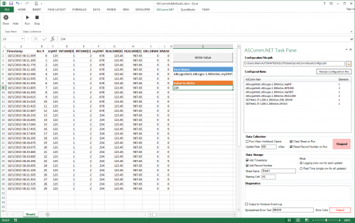
ASComm Excel Add-in is a simple to use, non-programmatic way to populate Excel 2007 - 2021 (version 16) spreadsheets with data from PLCs, instrumentation, and other process hardware. ASComm Excel Add-in uses built-in drivers for Modbus/TCP and Modbus RTU/ASCII communications. No OPC, DDE, external drivers, or programming required -
[Demo Software] - Excel Add-in for Modbus/TCP Data Logging
Automated Solutions posted a topic in Download Comments
View File Excel Add-in for Modbus/TCP Data Logging 3.6.8 ASComm Excel Add-in is a simple to use, non-programmatic way to populate Excel 2007 - 2016 spreadsheets with data from PLCs, instrumentation, and other process hardware. ASComm Excel Add-in uses built-in drivers for Modbus/TCP and Modbus RTU/ASCII communications. No OPC, DDE, external drivers, or programming required Submitter Automated Solutions Submitted 03/01/16 Category Demo Software -
Version 3.11.2.0
84 downloads
ASComm Excel Add-in is a simple to use, non-programmatic way to populate Excel 2007 - 2021 spreadsheets with data from PLCs, instrumentation, and other process hardware. ASComm Excel Add-in uses built-in drivers for GE / Emerson PACSystems (RXi, RX3i, RX7i), Series 90 (90-30), and VersaMax communications. No OPC, DDE, external drivers, or programming required.
.jpg.ab4bdacbd75415ee4a44ee0400895a6a.thumb.jpg.83cdde1f1a77c9aa8bca447d6c02783b.jpg)