Search the Community
Showing results for tags ' comm. settings depending on hw used.) connect any mb client/master or server/slave device(s) to your clgx plc'.
Found 132 results
-
SIMATIC S7-300 training kit not working. PLC doesn't go to RUN mode, and still in STOP mode all the time. STOP mode led is blinking every 1 second, even when I press MRES key. This is a video I recorded for issue demonstration: https://www.youtube.com/shorts/ISMPH_zNuG4
-
Hi there! I'm trying to communicate a Weintek cMT2128X with a CP2EN via Ethernet. The thing is I'm getting 'No device response' messages every 2-3 seconds. They'are connected at some point because some values are updated, but the connection error keeps showing up. So far I've checked: - Comm. settings are okay in both sides - Wiring is good - Happens the same with a CJ2 CPU. - There are two arrays of 50 UINT each, I don't know if that's slowing things but that would surprise me... I've worked with Weintek HMIs before (communicating with different CPUs: LOGO!, CP1, CJ2...) and never had this problem. I just set the IP addresses and everything was working fine, so I guess I'm missing something. Hope you can throw some light at this! Thanks in advance
-
Hi all, I would like to know how to communicate scale indicator device mettler Toledo ind 320 using module QJ71C24N-R4 by predefined protocal I also tired to communicate in CH1 with the G.INPUT instruction to communicate when the device in MT continue mode it does communicate but I dont know how to convert value Now by trying modbus communication predefined protocal works fine but i cannot read data the is no SD/RD transmission happening Can anyone help me with this Thank you serial monitor.gxw serial monitor.gxw
-
Hi guys I have a application developded in c# and communicate to PLC CJ series through cx-server 5.0.5.2. So, now I want use a NJ series but in the combo box on cx-server not have NJ series... just CJ, C200, etc Any suggestion? Thanks in advanced
-
Hi, We are receiving an error "*Error** PLC of all MODBUS/TCP connection modules Port No. is mismatched. When using multiple MODBUS/TCP connection modules, PLC of all MODBUS/TCP connection modules Port No. must be matched. MODBUS/TCP Connection Module NV_E02435" while trying to add two slave connections with different port numbers.....Please clarify on this error...
-
Hi All, As a system integrator coming from an Allen-Bradley based environment to a Mitsubishi based environment (GX Works 2, Q series PLCs), I am used to doing this with Allen-Bradley PLCs: when you hit save while online, you are prompted to upload the values in the tags and can save these values and view them offline - which is useful when doing modifications and analysis offline, as well as backing up settings in case your PLC dies and has to be replaced with a brand new one. I was wondering if anyone knows if there is a way to store the current values of the devices in a Mitsubishi PLC to my PC along with the .gxw file that is saved when doing a "Read PLC"? I am aware you can set up a File Register but it seems to only save ZR devices as well as specifically designated "Extended Data/Link" D and W devices, but most data is not stored in these devices. Thanks
-
I have been trying with an Ethernet cable and a 1747-pic i am 100% sure there is user error need to download a program into the PanelView i have the correct software rslinx and panelbuilder32 help I'm trying to learn
-

there is a device in the program (main) that is outside of the range
techsupoortalpha posted a topic in Mitsubishi
Hello, Good Day All. I am facing this issue while I am going to copy old plc to new plc. but old plc having 4965 steps, once going execute this program to new plc its showing more than 8000 steps. please suggest on this. PFA. -
Dear all member forum plc , Hello anyone can suggest me,how to communicate QJ71E71-100 WITH OPC Takebishi,How to to configure parameter on QJ71E71 -100 and OPC server Takebishi,I Want to aqcuisition data machine to database,
-
{[Demo Software] - mitsubishi nexgenie plc target settings
lionheart86 posted a topic in Download Comments
mitsubishi nexgenie plc target settings View File This target setting files are used with codesys software for programming mitsubishi nexgeine PLC series, Submitter lionheart86 Submitted 01/18/17 Category Demo Software -
Can USB-A2 connect PLC through PROFIBus? Can profibus connect sub-stations directly for diagnosis? There is a 3152dp, which communicates with the sub-station through dp, and it is inserted into the dp head of cpu. It is not connected by automatic mode, but can be inserted into mpi port. Do you need any Settings?
-
Hello fellow tinkerers, Inside our company we're expanding our IoT network with the replacement of CJ1G-H to CJ2M CPU units. When swapping models we are downloading the Datamemories back into the CPU. Our engineer warned us to not download all the DM memories: only up to D20000, so I did. When starting we had some inputs that weren't showing in the Data trace: and noticed that it were pulses shorter than 8ms. We found out the "Unit settings" were back to default and this is not unusual since we only downloaded range D0-D20000 but I'd like to avoid this in the future and look up what each datamemory means. I know D30000 to D31599 are the memories for the CPU bus unit settings (manual W473 section 4-5) but what range is the "unit settings" within these 1600 datamemories? I can't seem to find it in any manual I look into (W473, W472).. Also do you see any problems with downloading the full datamemory range? Kind regards!
-
Hello people! I'm working on a project that part of it, is to send data that are collected in the PLC, via email to office. The PLC and HMI I use (NX1P2 and NB series),they do not support any email instruction, unfortunately. To overcome this obstacle, I decided to forward those data (saved in .csv file) by using the FTPPutFile instruction and to upload the csv file from PLC to a dedicated folder to the office computer. PLC will be the client (passive) and the computer will be the server. And here is where I need your help.. The set up is offline by using a dummy ethernet switch. I set an IP address in the computer, as well as to the PLC side. If I set the PLC as a server (FTP server ->use -> port 21,pass & username), I can connect from the office computer to the PLC and download the file, by using cmd. When I try to use PLC as a client, Ftpputfile instruction always gives errorid 2407 and erroridex 00000226. In the FTPPutFile instruction box I set the following: ConnectSvr: IP address of PC, port 21, username & pass SvrDirName: the physical path I set when I configured the FTP site on PC (C:\...) LocalDirName: '/' FileName: '.. .csv' Further more, in the file explorer I type ftp:\\(IP address of PC), I log in but when I try to create a new folder 550 error is coming up (I suppose this is for permissions). Am I missing something? Do you have any suggestions/guide for making this work? I am not an IT and I am not experienced in that field so any help would be great! Thanks! Man31
-
Hey guys. So, I purchased a used copy of AutoCAD electrical but its all in French. Somehow I stumbled through the installation but I can't for the life of me figure out how to change the language settings or if it was in the install. If anyone has a similar year version and could possibly tell me the menu breakdown to get to the language settings I would very much appreciate it!
-
Hi All, Has anyone had the experience of connecting two Fernhill Scada units using an OPC UA? I am intending to use Fernhill Scada on my Master PLC to read tags from my Slave PLC's Fernhill Scada. Then, displaying local tags (Master PLC, "Fernhill SCADA Unit 1") and read/scanned tags from the Slave PLC, "Fernhill SCADA Unit 2". In the meantime, I am trying to use both of my Fernhill SCADA units interact with each other (one unit to read tags from the other unit) by using Internal Digital Tag on the Fernhill SCADAs. Any help would be appreciated.
-

[Demo Software] - Modbus/TCP Client Driver Library for .NET 8.0, 7.0, 6.0, 5.0 & .NET Core 3.1 - ASComm IoT
Automated Solutions posted a topic in Download Comments
Modbus/TCP Client Driver for .NET 6, .NET 5 & .NET Core. - ASComm IoT View File ASComm IoT for .NET 6.0, .NET 5.0 & .NET Core developers. Class library for use in Visual Studio.NET to create HMI/SCADA apps that communicate with Modbus/TCP Server devices via Ethernet. Does not require OPC or 3rd party drivers Visual Studio.NET 2017, 2019 and 2022 compatible All .NET 6.0, .NET 5.0 & .NET Core targets are supported, including Web, Windows, console, and service apps. Runs on Windows, Linux & Android Extremely high performance - 5~10 mSec typical transaction time Supports Modbus functions 1, 2, 3, 4, 5, 6, 7, 11, 12, 15, 16, 17, 20, 21, and 24 Address mode support includes: Zero-based, One-based, Modicon 5-digit (1, 10001, 30001, 40001), Modicon 6-digit (1, 100001, 300001, 400001) Abstract base classes allow you to write generic code that works with all drivers Synchronous and asynchronous read/write methods Data change notifications Provides common user interface across all driver classes No limit on number of devices or data points Multi-threaded for high data throughput Includes extensive help system Example applications with VB and C# source code included. Easily connect office systems to factory floor. Runtime-free for qualified applications Submitter Automated Solutions Submitted 05/18/22 Category Demo Software -
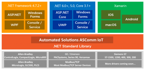
Modbus/TCP Client Driver Library for .NET 8.0, 7.0, 6.0, 5.0 & .NET Core 3.1 - ASComm IoT
Automated Solutions posted a file in Demo Software
Version 1.4.1
34 downloads
ASComm IoT for .NET 8.0, 7.0, 6.0, 5.0 & .NET Core developers. Class library for use in Visual Studio.NET to create HMI/SCADA apps that communicate with Modbus/TCP Server devices via Ethernet. Does not require OPC or 3rd party drivers Visual Studio.NET 2017, 2019 and 2022 compatible All .NET 8.0, 7.0, 6.0, 5.0 & .NET Core 3.1+ targets are supported, including Web, Windows, console, and service apps. Runs on Windows, Linux & Android Extremely high performance - 5~10 mSec typical transaction time Supports Modbus functions 1, 2, 3, 4, 5, 6, 7, 11, 12, 15, 16, 17, 20, 21, and 24 Address mode support includes: Zero-based, One-based, Modicon 5-digit (1, 10001, 30001, 40001), Modicon 6-digit (1, 100001, 300001, 400001) Abstract base classes allow you to write generic code that works with all drivers Synchronous and asynchronous read/write methods Data change notifications Provides common user interface across all driver classes No limit on number of devices or data points Multi-threaded for high data throughput Includes extensive help system Example applications with VB and C# source code included. Easily connect office systems to factory floor. Runtime-free for qualified applications -

NX1P EtherCAT Master to Beckhoff EtherCAT Coupler
TigerLily posted a topic in NJ Series / Sysmac Studio
Hello! I am working on a quote for a new project that will use EtherCAT but also requires DeviceNet for some legacy components. Has anyone successfully used the Beckhoff EtherCAT coupler (EK1100) with the DeviceNet Master Terminal (EL6752) and an Omron PLC as the EtherCAT master? My concern is that the coupler will only communicate with the Beckhoff EtherCAT master, but since it is so much more expensive to get the new Omron parts to communicate DeviceNET i am hoping this could be an option. The equipment is extremely simple and price is a major consideration. Thank you!!! -
Hi, I have a problem with Omron PLC and Beckhoff IO. The IO just disconnects in a few minutes and comes back! I received different errors: Link off error, Illegal slave disconnection, process data reception timeout. When I also check "Display Diagnosis/Statistics information" I see errors on all ports A and B of all nodes. I have called and talked to both Beckhoff and Omron. I have two NX1 and one NJ101 to test. And I have three EP2318-0001. I have the same problem with all the PLCs and EP boxes. It does not matter if I have one, two, or three nodes. I have tried different revisions of the EP2xxx from the XML file, different settings for the slave, different task periods, and the error still is persisting.
-
Hello, We want to do excel reports on Siemens PLC. We do not want to use historian programs. Do you know another programs?
-
Hello to everyone. I hope you are doing well. I'm trying to establish a communication between my PC and my KINCO PLC. The manual states it supports MODBUS RTU protocol, so I downloaded two different Modbus Master simulator I found out: Multiway from OMRON and qModMaster. None of them seem to work properly. I attached some pictures of the messages I get. https://ibb.co/f1mCSNt Multiway message https://ibb.co/bP5cX1t qModMaster message I include the configuration of the communication parameters. https://ibb.co/nMty8D9 PLC parameters https://ibb.co/6RTqVfC Multiway parameters https://ibb.co/N1XTccd qModMaster parameters According to the manual, in order to play the role of Modbus master with the PLC it's necessary to configure some instruction blocks (I'm programming in ladder). However, I could not find any block to configure as Modbus slave. I don't know what else I can do. I'm in trouble with this task. Am I making some mistake? Thanks for your attention. Kind regards!
-
hi everyone i have a question about nx ec0122 i connected an encoder to ec0122. now i want creat a programm for read the pulse and reset pulse. Then write a program to measure the length of a roll. How should I do this? Thank you for your help
-
Hi all, looking for some help. Have been using WonderWare since version 7.1. We currently use WonderWare 2020, but some of our products still require 2014 R2. Here lately, I have had trouble installing WonderWare 2014 R2 on Windows 10, specifically the SQL 2014 install. I have attached an image of the error message. I have tried multiple different methods to resolve the issue including pre-installing different versions of SQL Server. Thanks all!
-
Communication/configuration problem with AB PLC and Balluff smartlight
DoctorFrogman posted a topic in Allen Bradley / Rockwell Automation
Hello fellas. I am having trouble with understanding the communication between my AB PLC and my Balluff BNI0085, which is connected through an IFM AL1120 IO-link deivce. I am currently running a setup with an AB PLC (L18ER) that is connected to a local network through a network switch. I have connected my IFM AL1120 to this switch, and the IP configuration for both devices have been completed. The communications are made by using two add-on instructions, supplied by Rockwell: The BMC_AOI_PROC_BNI0085 instruction (For the Balluff smartlight), and the Generic_4PORT_IOL (For the IFM IO-link). I have additionally been supplied an ACD-file by my ex-coworker, containing a program that administrates the communication between the two add-on instructions. I have attached the routine from this as a PDF. What works: I can go online with my PLC, and by using the parameter "BNI0085_Mapped_Data.O" I can control the smartlight. I can change the settings for light-mode (Segment, Level, Runlight, Flexible), and the different parameters for each mode. What's the problem: When I change the Mapped_data.O to run in level-mode, I can adjust the light to show the level desired. When I try to adjust the level above halfway, the light switches off, and can't seem to be steady lit (Light turns on/off, random dimming). I speculate this might be due to the small power supply for the IO-link device, and the setting for brightness is not included in the AOI for the smartlight. I therefore tried to adjust the brightness by connecting through the LR-device software from IFM(The same used to configure the IO-link). I added the IODD (IO-link device description, "Balluff-BNI_IOL-802-102-Z037-20190215-IODD1.1.xml") for the smartlight, and connected the device, which is discovered in the device list once the IO-link IP has been entered. I can read the values from both the IO-link and the BNI0085 devices, and I can write parameter settings to the IO-link device. Whenever I try to edit any parameter for the smartlight, I get the error attached. I am currently trying to follow the SmartLight userguide for the Balluff, as it describes the brightness setting as being in the ISDU index 51hex, but I don't know how this pertains to the AOI. I am in over my head with this issue, and I don't know what information is needed or what is unnecessary. I've tried to include all that I think is relevant, I'll gladly provide what might be missing. Any help is greatly appreciated, cheers :) Balluff_smartlight_com_MainRoutine.pdf -
I am using Factory talk view to practice but there is not any physical HMI ,I have been come up with errors. So,I am not sure to create new HMI server ,it requires physical HMI?? THANKS