

olivier123
MrPLC Member-
Content count
20 -
Joined
-
Last visited
Posts posted by olivier123
-
-
On 5-4-2021 at 8:09 PM, IO_Rack said:Nice! Thank you for your results.
I was actually wanting to try this myself as a home project on a Raspberry Pi. I'm glad to see others have success with it.
It looks like it works except I don't have the correct IP-address.
See attached image. The 169..... IP address is the one I used. I also used 192.168.250.2, but that didn't work. After running the program with 169... IP nothing changes in the PLC registers, so I think I need to look further into that.
@Michael Walsh do you have more knowledge about this subject?
Image link: https://ibb.co/r60YVJs
I wasn't able to insert media through this forum...
-
2 hours ago, IO_Rack said:Do you know the IP address of the CP1L-E?
Do you have CX Programmer?
I have not tried using the software in the link I provided. The user in the link had success. Also the author has provided his email address.
Yes, I put the address 192.168.250.2 as IP in the PLC settings, that should be the correct IP, right and I'm using CX-programmer.
I sent an email to the author and he already answered. I should have downloaded the files separately instead of using pip install fins. So that's solved now.
-
On 31-3-2021 at 7:29 PM, IO_Rack said:I was unaware the CP1L-E was capable of Socket Services. This is an option.
Since you are using Python, have a look at the link below.
https://forums.mrplc.com/index.php?/topic/39456-omron-plc-cs-cj2-read-write-data-over-python/
This link helped me quite a lot, but I still have some problems
1- It looks like that pip install fins didn't fully install the whole library, because I still got some error during running the program. I think that's solved now luckily.
2- After running the software I receive a 'timed out' message, which is probably caused by an incorrect given IP-Address. I have tried many addresses, but it seems like nothing is the correct IP. Maybe this problem has something to do with 'problem' 1 which I stated above. -
On 31-3-2021 at 5:31 PM, photovoltaic said:You may be better off with socket services:
Thanks for your answer, I will take a look at it
On 31-3-2021 at 7:29 PM, IO_Rack said:I was unaware the CP1L-E was capable of Socket Services. This is an option.
Since you are using Python, have a look at the link below.
https://forums.mrplc.com/index.php?/topic/39456-omron-plc-cs-cj2-read-write-data-over-python/
Also thanks for this option. I will try both and hopefully I'll find a working solution! When i have everything working I will post what I did
-
43 minutes ago, IO_Rack said:I'm not familiar with OpenCV or Python but I would have to believe the communications will be much more efficient exchanging Bytes or Words. I would dedicate a Word to the Booleans you wish to exchange.
For reading and writing you would need to perform Logical operations on the Word to extract the Boolean. The CP1L has advanced instructions for this but with Python you'll likely have to do it discretely.
Using words would be no problem, 0='N' and 1='Y', but using RECV and SEND should work?
If anyone has more information about how to do that, I would love to hear more about it, thanks!
-
Hello everybody,
I have another question! I've made a computer vision program to check if a roller (for conveyers) is defect. The software is written in the Python programming language (with the OpenCV library). What I want to do is: I want to send a boolean (0 or 1) from Python to my Omron CP1L PLC. A few years ago I did this with a Siemens S7 1200 PLC with the socket library. Is that also possible with the Omron PLC in combination with RECV/SEND instructions, if yes how and if no what is a good alternative?
Thanks,
Olivier
EDIT: I also need to receive a boolean on the Python side
-
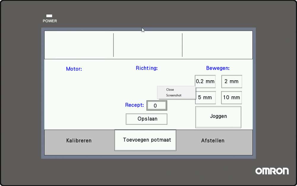
On 5-3-2021 at 11:19 AM, Robror said:How about the Direct Screen part? You can associate a bit to the task finalization and the selected screen will pop up. NB's manual has more details of this tool.
At least, I can try...
EDIT: That worked, thanks!
-
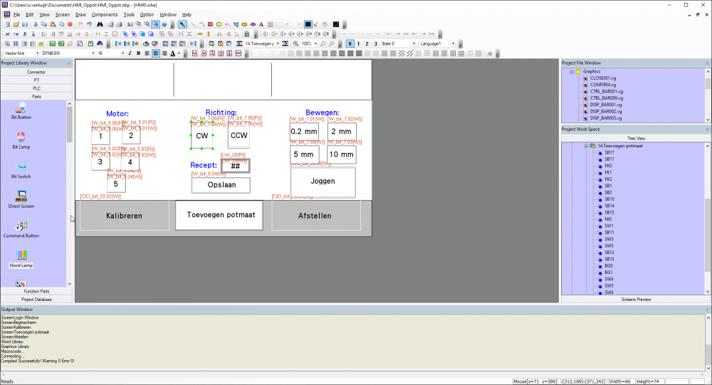
Hello everybody,
I've been searching for a solution for this problem, but haven't found it yet. When the user is done with a task, a certain bit turns ON. Then a poppup should popup. I tried using alarms, but that won't work, because I have to initialize an alarm display on every window I've made.
Can somebody help me?
Thanks,
-
Hello everybody,
I continued my project this morning and my HMI gives the 'PLC No response 00-02-3" error... I haven't changed anything since last Friday, so in theory it should work. I used this tutorial a few weeks ago and that worked. I also tried so use some old programs which used to work, but they don't work now...
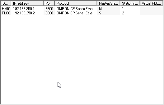
HMI IP: 192.168.250.1 (the addresses from the tutorial)
PLC IP: 192.168.250.2 (the addresses from the tutorial)Does anyone know what could be the problem? I already tried using another switch, but that didn't work either.
EDIT: I just saw that I posted this in the wrong subforum, excuse me
EDIT2: I found the solution. I cleared the data memory before... So what I did was transfering the settings to the PLC, then completely power off the PLC and then power it on again. That worked for me!
Thanks,
Olivier
-
15 hours ago, Michael Walsh said:I am surprised that it even lets you put that in for a default gateway. That is definitely an invalid IP Address.
I searched around on the internet and I noticed that, so I'll change it to a valid address
-
I don't have a communication yet, so that could be the issue. Still having issues with the communication. I have used this https://www.myomron.com/index.php?action=kb&article=1539 omron article to set my communication, but i still get the PLC no response error on the HMI. Any tips to solve that specific problem? After solving that problem I can take a look whether the communication resolves the problem with the bit switch. Btw I have put the PLC0 IP address in the PLC, so that's definitely not the problem
EDIT: I changed the default gateway to 0.0.0.255 and the communication worked. I'll take a look if the bit switches will also work
-
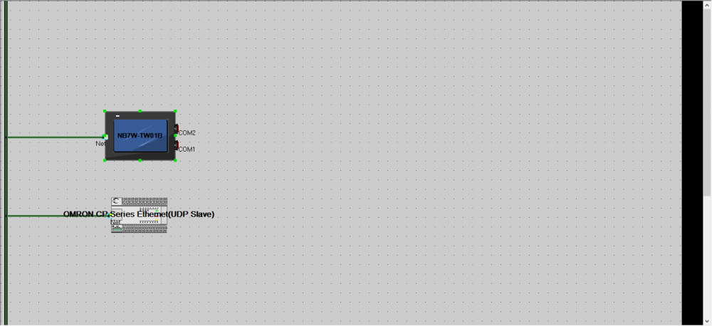
Hello everyone,
I am creating an HMI in NB-designer, but I can't use the bit switches properly. I can use the Local Bit memory, but when I switch to W-bit memory, all the switches will disappear. Does anyone know how to solve this problem?
Thanks,
-
Hello everybody,
I reinstalled CX-programmer yesterday and installed it again and it worked without any problem. I wanted to open CX-programmer this morning, but it didn't. However, I can run CX-P as Administrator, but then I don't have access to my files. CX-P gives this screen when trying to open it:
Does anyone knows how to solve the problem? I already reinstalled CX-P today and also restarted my PC.
Thanks in advance,
Olivier

-
I got the stepper motor working! :) However, I want to turn the motor driver off (HIGH), because my motor won't get any pulses in that way. Is there a possibility that a bit will get 0 or 1 when the PLS2 is done? So I will turn my driver on, then I will send the pulse train, then the PLC makes a workbit 0 or 1 and then it turns the driver off.
-
Okay, I'm back with another question. I am quite sure that I use the CP1L-EM40DT1-D PLC (PNP --> sourcing transistor output) and I am using a Leadshine DM556 ( http://damencnc.com/userdata/file/1750-1_DM556_datasheet.pdf ) motor driver. When I wire the driver with the 'active high' (page 5, figure 2) connections to the PLC, the PLC always has a ~24V output. Is this because you cannot connect active high to a PNP PLC? Which means that I need to wire the driver to the plc according to figure 3?
-
@all Thanks for the answers!
In that case, I have another question. I will probably use this drive: https://www.damencnc.com/nl/closed-loop-stepper-drive-es-d808-80v-8-2a-2phase/a922?c=123
I should connect a PTO (or PLS2) to the PUL+ input, right? Should I connect a 'normal' output (0 or 1) to the DIR+ input or? I've never worked with PTO's before, so that's why I'm asking. Thanks! -
1 hour ago, Michael Walsh said:You cannot use relays for high speed pulse outputs. They not even close to fast enough and will not last very long as the mechanical life of a relay is short. To be able to independently control 7 steppers you will need 7 pulse outputs.
No, but I won't use a relays to 'generate' a pulse. As you can see in the image below (I know that it has some mistakes), I connect (in this image) 3 relays in series. If I want to control the first motor I activate the first relays. If I want to control the second motor I deactivate the first relay and I activate the second relay. The relay is only used as a simple switch.

-
Hello everyone,
I am currently working with a CP1L-EM Omron PLC and I must control 7 stepper motors with encoders with a (not yet determined) stepper driver, but probably a hybrid stepper driver, because they allow encoders... (https://www.damencnc.com/nl/closed-loop-stepper-drive-es-d808-80v-8-2a-2phase/a922?c=123). To control the motor driver I should send a pulse to the PUL+ input or is it also possible to send a very high-frequency signal to the input, so a 200 Hz signal (or more) 5V - 0V - 5V - 0V. If no, the CP1L-EM only has 4 PTO's, but I should control 7 motors, so I need 7 PTO's... I thought that it might be possible to use 1 PTO and send a pulse to a motor driver and then use a relay to send a pulse to another motor driver, is that possible? If no, what is the best way to control the motors?
Kind Regards,
Olivier


Sending boolean with RECV/SEND instructions? [Python&CP1L-EM]
in CX-Programmer
Posted
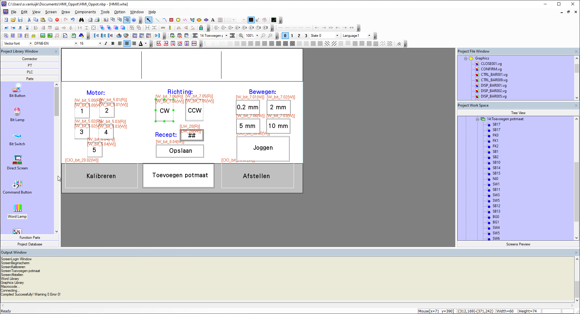
Okay I finally got this working! I used Joseph's Python Library.
This is what I actually did and it works really good. Thanks for all your help, very happy with this result!
If anyone has questions, let me know and hopefully I can answer them.