

T J SHARON
MrPLC Member-
Content count
52 -
Joined
-
Last visited
Posts posted by T J SHARON
-
-
HI all,
managed to settle. Some of the TX words were integars. I changed to UINT. Issue solved.
Any suggestion or comments?
-
HI all,
Any suggestion or comments?
-
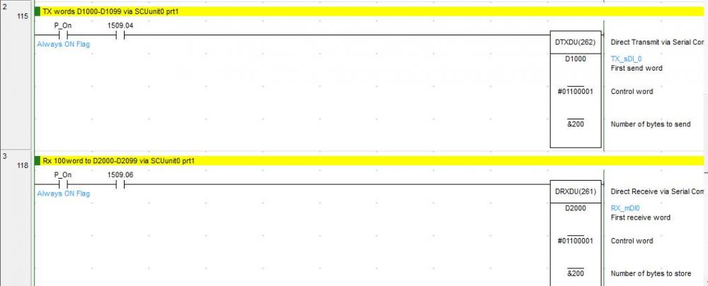
HI All,
I have an issue with my SCU32 communication.
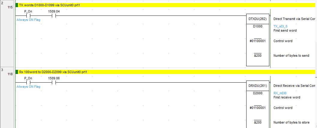
Back ground
Two SCU32s (top and bottom side) connected via a 1100M datacable using port1 ( 9600bps, 8-2-E, start code FF, end code FE, Tx save to d1000-d1200 , Rx save to d2000-d2200). PORT2 of bottom SCU32 is connected to a compass( 2 wire, 8-1-N, 19200 bps, serial gateway MODBUS ). Refer to photo
Issue
Without compass, the receiving data at top is very stable and is didn't see any fluctuation. But if is compass is connected at bottom side port2, there is a fluctuation at the top side RX data(specifically d2000-d2005 ) . I checked the data a bottom side TX (d1000-d1200) and it is stable. Only after sending the data and Receiving at Top side, then only the starting words fluctuate.I am not sure sure what is wrong, I am using logical ports for the DTXDU/DRXDU and compass.
Appreciate all your feedback and suggestions.

-
Thanks a lot
-
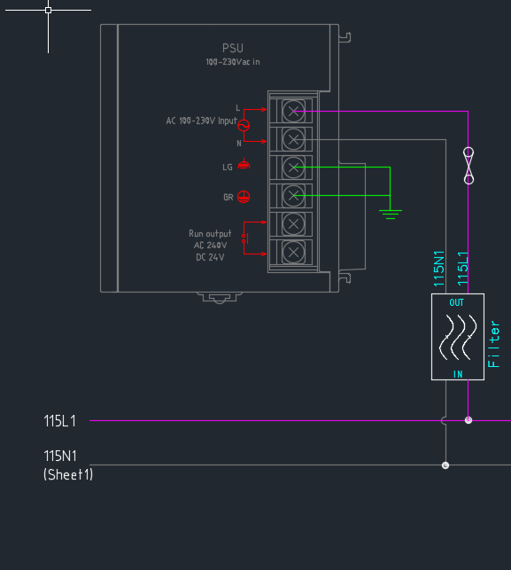
HI all,
Is there anything issue or wrong in thing connection ( added noise filter & fuse. )?
-
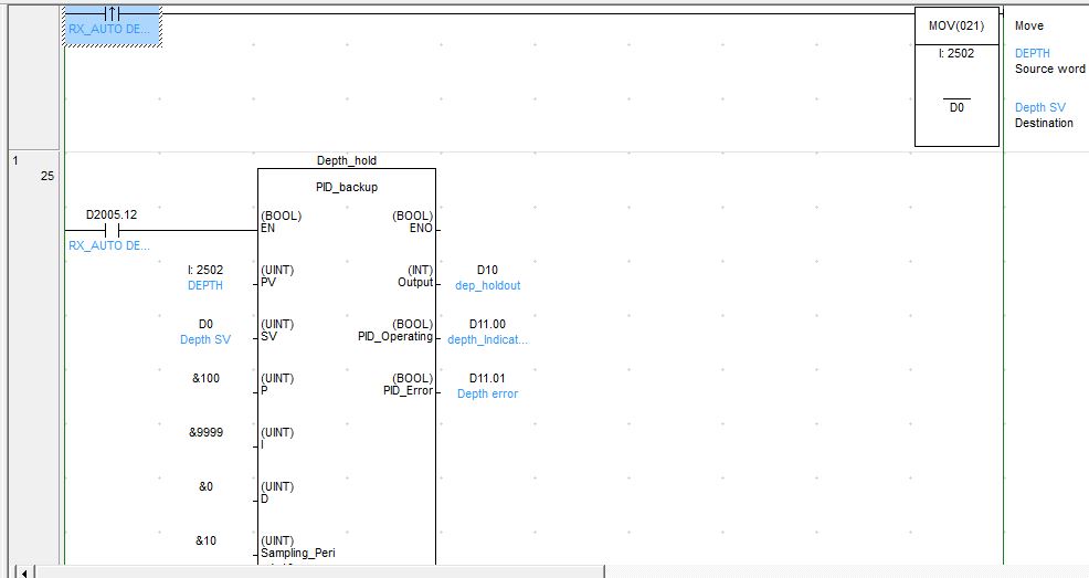
Hi,
I am using same ADunit channel ( 2502) for SV & PV in the PIDAT instruction. When the execution start the DIFU will save the current value as SV.
I am suing AD081 and PLC read as UINT 0-4000. My doubt is Do i need to scale the 0-4000 to 0-4095 for the SV & PV.?
-
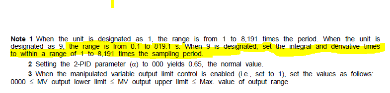
Hi All,
I need some clarification on the PID instruction.
The note states that if #9 is set for C+6 04-07, the I & D will be 0.1 to 819.1s. But I didn't understand this highlighted section.
Does it mean that my I and D values will something between (1x τ)~(8191xτ)s??
All help is much appreciated, Stay safe and healthy.
T J Sharon
-
Hi All ,
Thanks for all the reply and help.
let me try as what u said.
And thanks for sharing the video.
-
HI BOB,
"What is the analogue signal - 4-20ma? 0-10V? 4-20ma is much better for noise rejection - I will not use voltage analogues at all! Is the 24VDC supply negative grounded? That is always a no no as far as I am concerned - do not ground the negative at all but let it float - ground noise introduced. I expect the 24VDC supply is from a switch mode power supply. If so what brand? There is some really cheap junky stuff out there. Is the analogue cable only grounded at one end? It should be grounded at the source only. "
Based on red coloured statement how can i do wiring ? Something as below pic?
 1 person likes this
 -
Hi Chelton,
thanks a lot.
-
Hi ,
I already extended FB areas of H-memory. Is there any issue if I change my over all FB memory allocation to d10000 ?
Mean while I will try the feasibility of using IN-OUT method.
-
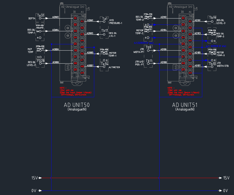
HI,
Its tested and working well.
I have 8 Analogue inputs and will be using 8FBs, which need 800 words for Buffer_Ring array.
But i don't have much free words in H-memory for Buffer_Ring array.
Is there any way that i can assign Dmemory for the array? ( Assign "AT" in the Fb variable session not possible as this FB is using simultaneously for different Analogue inputs)
-
hi Chelton.
Thanks a lot.
Let me go thru and work it out.
-
thanks
It seems like a code for FB.
Could you please specify the input,output and internal variables and data type? I managed to identify some.
- EN (bool) ------>INPUT
- Run (Bool)------>INPUT
- Ring_Buffer_Initialize (bool)
- Ring_Buffer_Write_Index
- Ring_Buffer_Read_Index
- Ring_Buffer_Size
- Ring_Buffer_Read_Index
- RB-Loaded (bool)------>OUTPUT
- ONS_Trig (bool)------>OUTPUT
- Ring_Buffer[ ] ------>INTERNAL
- Analogue_In (UINT)------>INPUT
- Analogue_Out(UINT) ------>OUTPUT
Appreciate all your help
Regards,
T J sharon
-
hi Chelton,
Mostly 1-5 seconds delay.
Do you have any sample prgm?
-
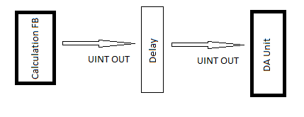
Hi all,
I have an FB (ST) which will calculate the UINT values that need to send to DA outputs. Currently i was requested to add a delay between the calculated output & DA units.
I am not sure how to do it? can I just use a TON? Any sample ST code?
-
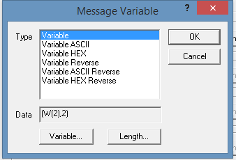
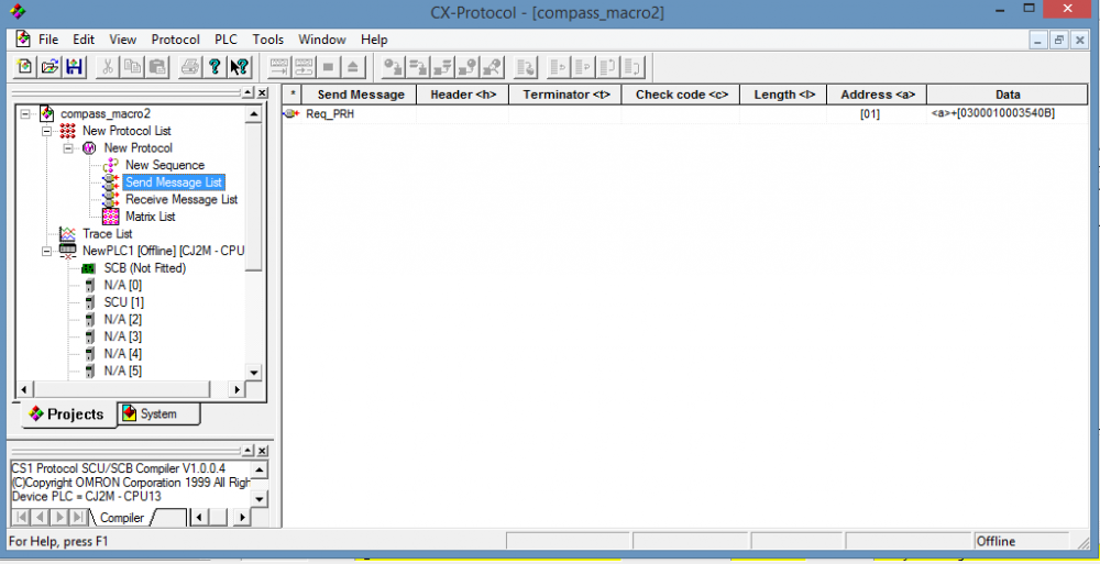
Hi all,
I managed to wrote the response data strings to data memory.
What i did was ,I changed the send and receive message data bit from 'variable Hex' to 'variable' in the CX Protocol file.
Now its working. I tried different combinations of send and receive messages. All worked well . ( refer to the attached pics).
 1 person likes this
 -
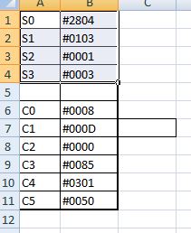
hi Dan ,
"The Modbus Function Code 06 is normally a "write single 16 bit register", so you'd have to write each register value one at a time with separate 'transactions'. "
How can i write it in each registers ? Should i write my protocol as " <a>+[0306]+&(W(1),2)+&(W(1+2),2)+&(W(1+4),2)+W(1+6),2 ' , which is (01 03 06 XXXX YYYY ZZZZ CRC)
1 person likes this -
Hi dan,
Thanks a lot. Let me try again!!
-
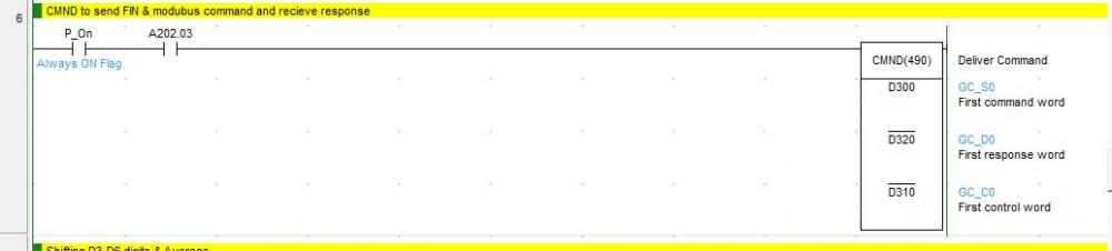
hi Dan & team,
So can I use MODBUS-RTU for SCU and General purpose device communication ?
Does it work if i follow the following ways?
- connect device to SCU
- Change SCU setting (MODBUS, baudrate , parity, etc).
- Use CMND instruction in ladder.
Thanks in advance.
-
-
-
Just noticed that 'No protocol; doesn't work with 2 wire connection.
So i will try to use cx protocol
-
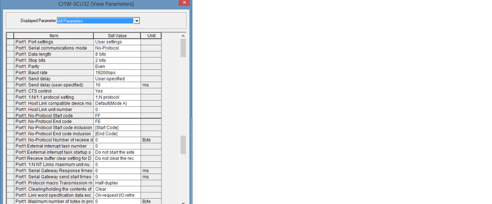
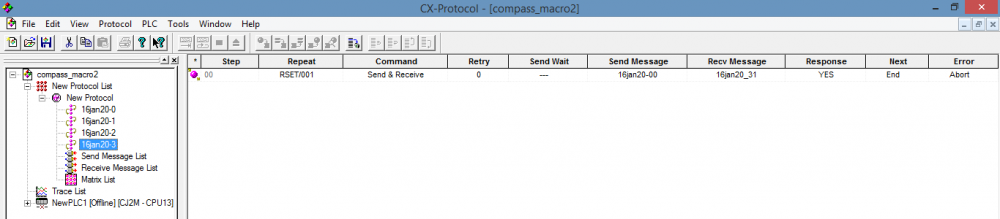
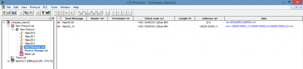
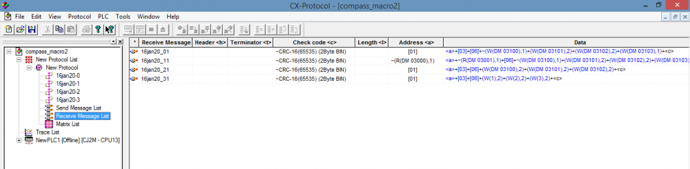
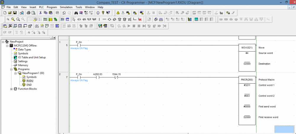
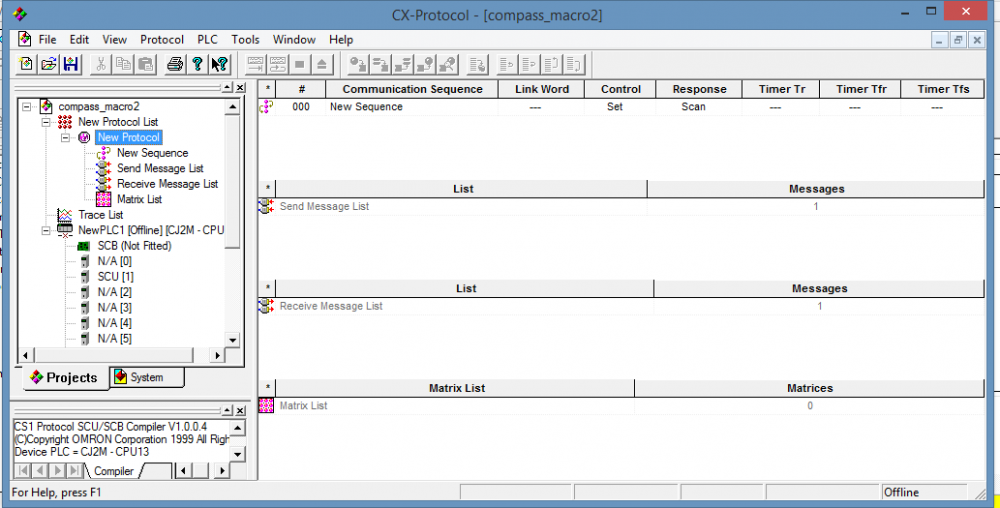
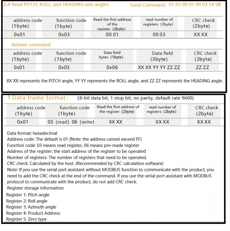
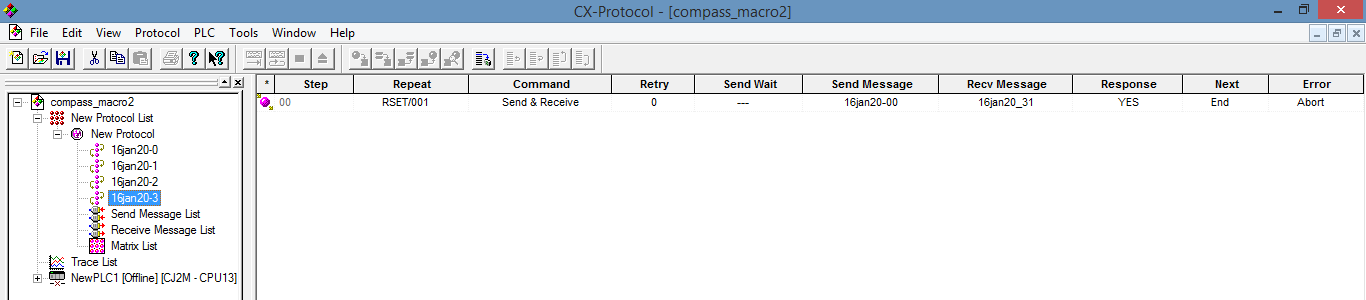
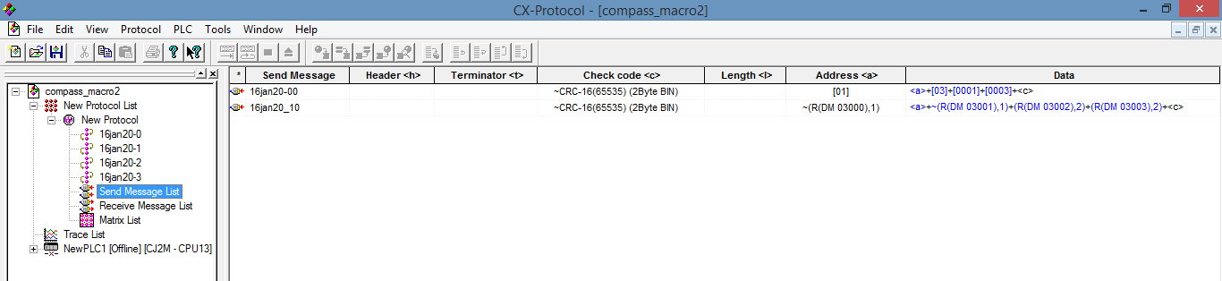
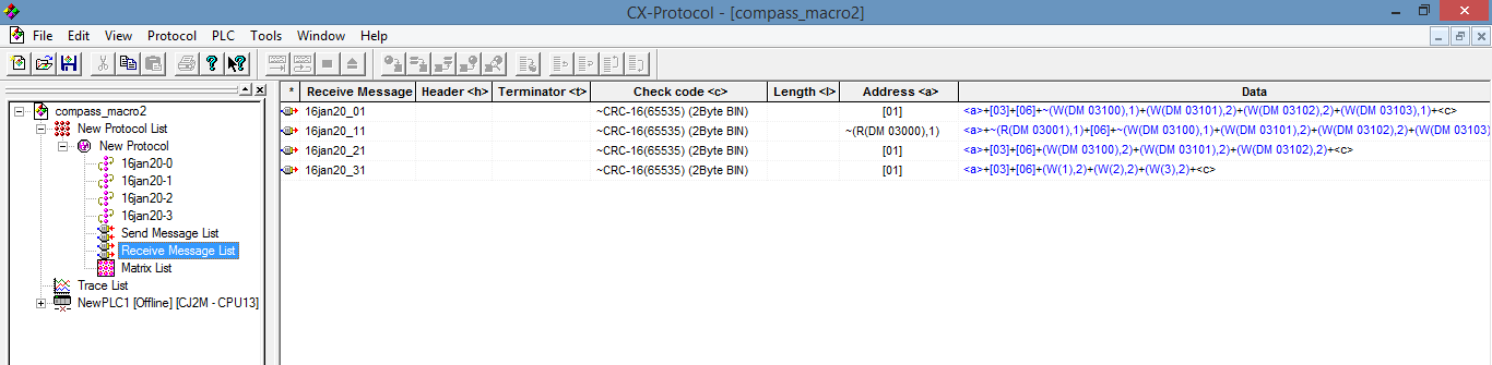
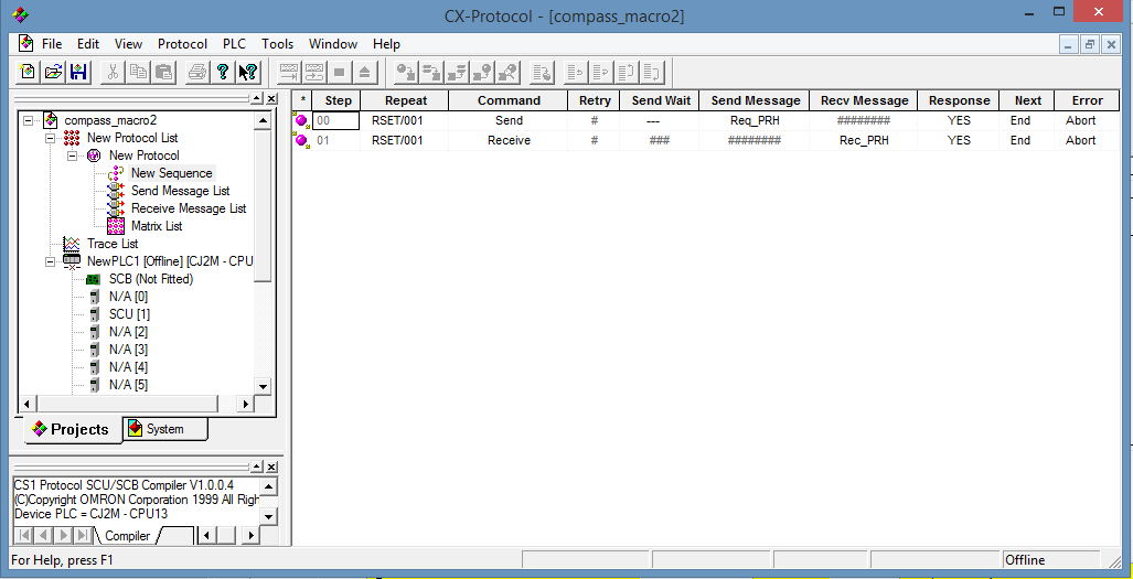
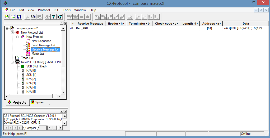
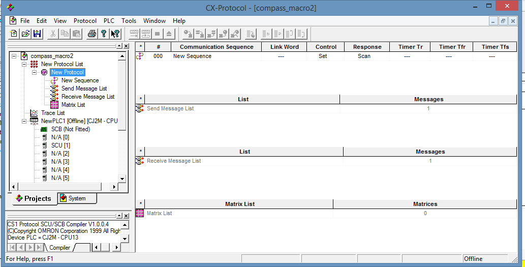
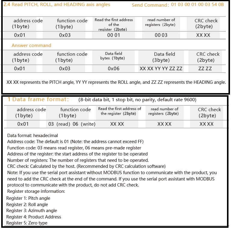
HI all,
I was trying to connect my compass with PLC via SCU32 RS485 (2 wire ) in protocol macros.[ Unit 1 port2]
My send command is " 01 03 00 01 00 03 54 0B' & Expected reply is '01 03 06 XX XX YY YY ZZ ZZ ZZ ZZ"
I created a new protocol using CX protocol and created a send message & a receive message command and added to sequence 000. (refer pics)
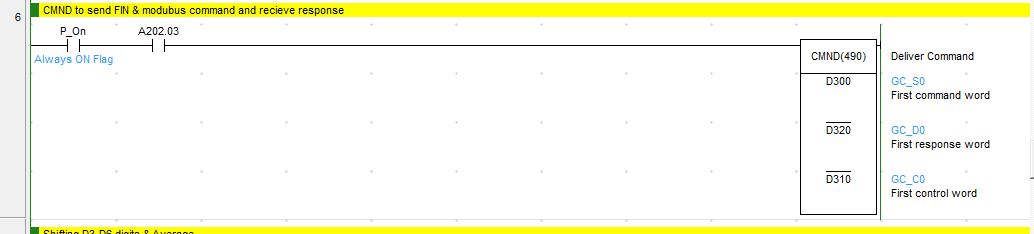
Also added PMCR instrcution in cx programmer (refer pic).
I can transmit the data , but i cant see any recieve data in D2000.
I am not sure what had done wrong, or am i missing something?
Any help is much appreciated!!


CPU to Advaced HMI slow response
in CX-Programmer
Posted · Edited by T J SHARON
HI all,
I have connected my CJ2M-CPU13 to Advanced HMI software via Hostlink (19200,7,2,E ) . I connected to the serial port in CPU and just used ( didnt write any code or formating).
The HMI response is very slow ( almost 2+seconds).
I am not sure whats is wrong, Is it because i am using more words?
Anybody had this encountered this problem?
Appreciate all suggestions and advices.