

Nyame Ephraim
MrPLC Member-
Content count
54 -
Joined
-
Last visited
Posts posted by Nyame Ephraim
-
-
Thanks panic mode, I will restructure the program.
but I need to use the count up. For accumulation and pre-set for my application.
-
Panic mode.
Okay thanks for the identification'
please how do I rectify this ?
-
-
Panic mode thanks for your contribution.
pulse width is 100 milliseconds I believe that's slow, secondly the reading from the flow meter aligns with the PLC HSC, but it's the CTU and HSC counts that does not align.
-
Hello all thanks for the Verious contributions.
After going through the program detaily I realize that the flow meter actually counts the same with my PLC HSC. But now my HSC does not count the same with my count up CTU.
For example the HSC is counting on 5 and CTU on 3
Please is there any possibilities for the both to count the same ?
-
Hello Sir, thanks for the reply
the HMI reads from the micrologix data table.
Am using Delta DOP B series HMI
-
Hello Sir, thanks for the reply.
am using E+H promag 50 that's flow meter and Allen Bradley 1400. In builder HSC.
thanks
-
Hi experts, the pulses counted in my flow meter are not the same with what is counted in my PLC.
my flow meter is set at 1 liter per pulse, and the pulse width is 100 mili-seconds
my PLC filter is set at 5 micro-seconds.
example for 12-13 seconds in my flow meter readings 23 liters will be dispense
for the same 12-13 second it shows 12 liters dispensed on my HMI.
please what settings are required to make both the PLC and flow meter count the same ?
am using high speed counter for this application.
Please i will appreciate any contribution to enable me solve this problem
thanks
-
Hi experts thank you people for the wonderful contributions you made. The program works well now
-
Hello, I noticed something, I configured the two counters in the same program but different ladders, the first counter and it register counters well.
the second counter only the Accumulator counts the destination register does not count.
Please will appreciate any contribution to resolve this suituation
thanks
-
okay i have PM you the program just now
-
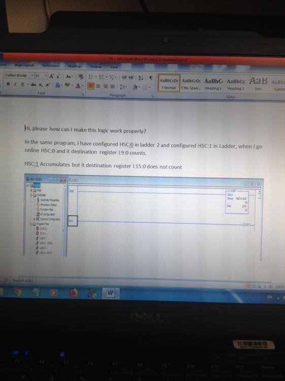
Hi b_carlton thanks for the contribution you have made, when i configured HSC:0.ACC, it was working very well and counting in the destination register L9:0, but when i configured the other HSC, for example, when i connected my square wave simulator input in IN 4 which reads HSC:1, I noticed only the HSC was accumulating, but the destination register was not counting.
i connected the pulse input back to IN0, that is HSC:0 Only the accumulator was reading and the register L9:0 was not reading any longer.
just thought of something, could it be that the battery am using to power my square wave generator is low ? and as such the pulses it generate now are weaker to work with the PLC scantime ?
-
Hi, my HSC counts accumulated pulses but destination register does not count !
will appreciate any contribution to help resolve this issue
thanks
-
Thanks for the video it helps.
Base on the video explanation, i came out with the schematic attached below, please kindly go through it. and see if i did it the right way.
thanks
-
Hello Pcmccartney 1, thanks for the video, but if i can get the wiring diagram it will help me more.
-
Hello, please i wish to simulate HSC in Allen Bradley 1400 using a square wave generator. i have built and tested the square wave generator it works well, the issue is how to wire it to Allen Bradley 1400.
also i wish to understand IO Configuration filter settings, am using Allen Bradley 1400 B series Processor
Thanks
-
Hello Sir, thanks for the reply. all the 4 inputs have been located and labeled as required. they are additional 4 inputs also used for flow rate. but i did not locate them on the data input file.
am doing direct verification's from the inputs and outputs once am done i will come out with documents identifying what input goes to were, and same with the output.
(nope... just need someone who has done PLC programming,. one person is plenty. you should be the one watching over the shoulder.) ( i studied electrical and control engineering, i did PLC programming as well, but am a fresher, coming across tasks like this builds me with a good experience) (remember the story of Thomas Edison and 2000 filament) once more sir thank for you constant contribution i appreciate.
-
Hello Sir thanks for the contribution. i need to understand the ladder logic diagrams first. looking at ladder 5 you will see real world outputs as indicated in the electrical diagrams. now looking at the inputs of the ladder diagrams they are made up of registers , in this situation how do i figure out the real time input. coz if you check the input data file, it show some inputs are ON but i cant figure their locations on the diagrams.
-
Hi, thanks for the reply, since ( It sounds like you really need someone to look over your shoulder as you work through this ) you are right. as it requires collective ideas coz the task is tough !
-
-
-
-
Hi, so far i got some documents from the manufacturer, while trying to study the documents, please i will still need more elaboration from this forum
thanks
-
Hi sir, thanks for the reply.
am working hard to get the documents.

Hi Experts, the pulses counted in my flow meter are not the same with what it counts in my PLC.
in Allen Bradley / Rockwell Automation
Posted
Thank you very much panic mode for the write up.
my goal is I wish to control flow. For example if I need 100 liters i should input the requirement in my HMI and once 100 liters is dispense The pump should stop, Different amount of litters maybe requested depending on the need.
Now my flow meter has been set at 1 liters per pulse, pulse width is 100ms and scan cycle is 3-5ms
that is the scope of the project
thanks