

Areeb
MrPLC Member-
Content count
68 -
Joined
-
Last visited
Posts posted by Areeb
-
-
hi, I wanted to install servo motor in my printing machine cylinder so for that I need to know how much "KW" servo motor is best for the cylinder. I have its diameter and weight. plz do let me know how I calculate the "KW" which is best fit for my cylinder.
-
Hi @Must@@@@ . You can go to the delta PLC software "Communication Setting" where U have to select RS485 option as a communication mode between PLC and HMI.
-
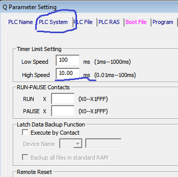
And plz also tell me what if I decrease the time below 10ms. and kindly see the below snapshots. what is it the correct place for changing the time ? PLC SYSTEM or I/O Response time ?
-
HI @Gambit. Can u tell me if I use interrupt program so how it will detect when there is no tape present in anyone of the sensor. As in current program the tape passes in front of the sensor and sensor will high then low then it again high and low in every scan of the program so in anyone of the scan if the sensor not goes to high state it will consider as there is no tape in current scan and it will high B1170 bit so rejection may occur. Plz tell how to program this logic using interrupt program.
Thanks & Regards
M.Areeb
-
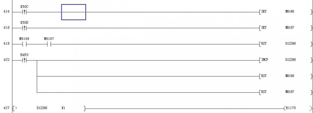
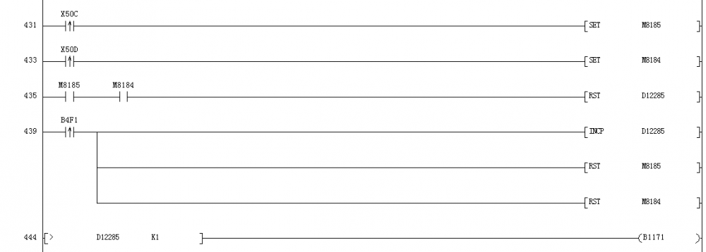
Hi Everyone. Hope u all are fine. Firstly I will let u know the my program details. The picture that is attached below is a part of my machine Q series PLC Program. It detects left and right tape of the product. Sensor X50C is attached in front of left tape and sensor X50D is attached in front of right tape. The program works in a way that it check the both left and right tape in one whole scan of the program. if during the scan if the tape is not present it will high B1170 bit otherwise it will reset D12286 and B1170 will reaming in low state.
The Problem i am facing is that sometimes it did not work correctly and misses the tape maybe can`t detect withing one complete scan of the program so I wanted to know is there any other technique by which i can modify this program and make this program simple and easy without involving the scan time period.
-
-
@Zamora I do not exactly know the distance but this might be the issue. can u please tell me what is repeater station and how to install it ?
-
OR sometimes this issue will gone when we take out the terminating resistor from the last module and then again place it in the module. we are using resistor of 120 ohms.
-
ok but I wanted to know one more thing which is that in order to solve the above problem we need to shorten the length by placing the module with their neighboring modules (because the error will give only those modules which are far away with other modules) or we just replace the communication cable of these modules.
-
Thanks all. I am using QJ61BT11N (Master) which is connected with PLC and all othe slave stations are AJ65SBTB-16DT and usually slave stations gives error and LERR light will blink. Furthermore I have check all the stations no and setting it is fine.
-
Hi everyone ! Hope you are doing good. I have one query related to CC Link Modules. I have a machine which consist of Mitsubishi Q Series PLC and with that there is also a CC Link module in which there is a loop of individual Communication Station. But the problem I am facing is that sometimes 2 of the communication stations gave communication error randomly, sometimes it works fine for about week or months but sometimes they will give error after one hour or two hour or 1 day. I did not understand the exact cause of this error whether it coming due to large length of wire between the stations or module faulty etc . can anyone let me know why this error occur and what might be the possible causes of this error.
Thanks & Regards
Areeb
-
Thanks buddy I will try to check it out with the given information above. Hope it will workout and solve my problem.
-
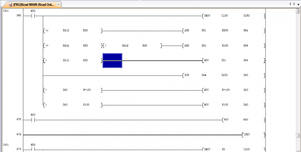
Hi, I wanted to know how do I check my interrupt input signal whether it coming or not. Basically I have a program which consists of I401 & I 501 interrupts as externally connected in X4 & X5 of PLC input and this signals belong to proximity sensor and photo mark sensor. But now it is not working properly as it is not cutting the product with the desired location. below I have attached the snapshot. I
-
Hi I have upload the program from mcgs hmi through USB. but when I open in my laptop it gives me this error; please suggest me any possible solution for that and tell me it is uploading mistake or 32 bit window needed for this ? the screenshot of error while opening the program file is attach below.
-
The program file which I have of this machine consist of some interrupt program but I don`t create it my own interrupt program before in this PLC.
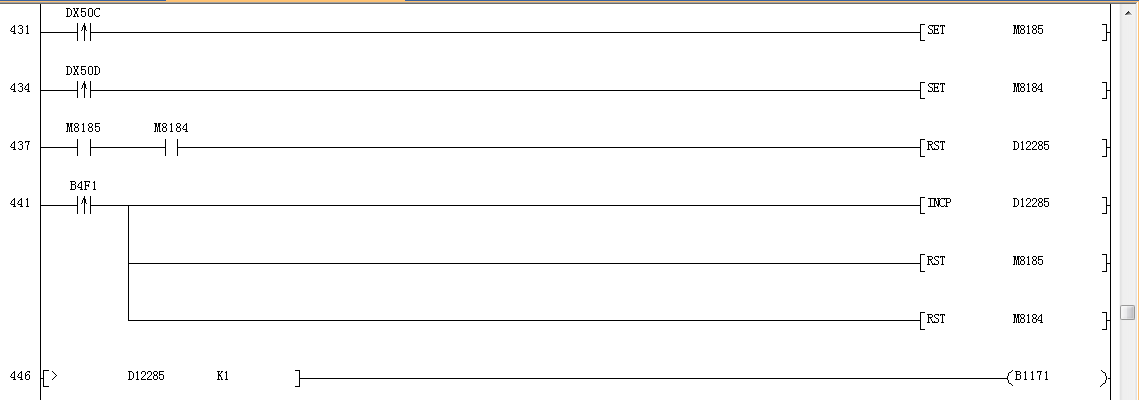
I have Modify the changes u said above kindly check in below pic is it okay will I try this one ?

-
-
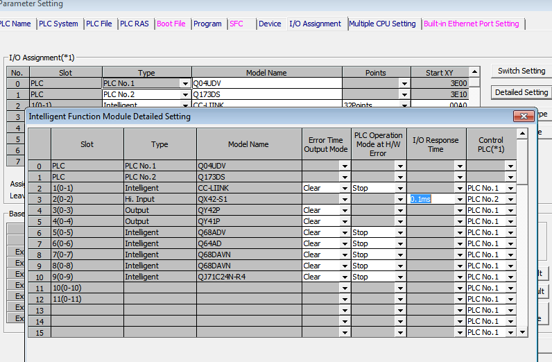
Yes u r right it is a part of regular scan program.
I have checked the response time it is already set to a lower value that is 0.1ms.
I am using Mitsubishi Q series PLC (Q03UDECPU).
-
Hi Everyone
I want some suggestion actually I have a machine which place left and right tape
in the product at same time. The Code picture is given below. It works fine in medium speed
but the problem is that when I increase the machine above 280 RPM so it will mal operate
due to which it gives the signal and consider the product having no tape on it and reject it.So my question is there is any other logic which I can use here instead of below so that
it will not reject the right product and it will sense in higher speed as well.
I don`t understand this why this problem occurring in higher speed.if there is any other logic which sense the tape individually please let me know.
please provide me any solution I will be very thankful to u.Left Tape Sensor 50C
Right Tape Sensor 50D
Thanks
-
Need your suggestion to find out the desired solution. basically I have Mitsubishi Communication modules attached in my machine. The last module gives error sometimes after
running 2 to 3 hours fine but after that it gives communication fault error in last communication module. However I have checked the cable and DIP swithces it all fine but if I changed the resistor it works fine for about 4 to 5 hours then after sometimes it again shows communication fault. So plz suggest me which value resistor should I place in last communication module and what are the possible causes of that problems ?Communication Module: Mitsubishi AJ65SBTB
-
-
I wrote here by mistake It is correct in PLC but still cant receive the voltage
-
Hi everyone , hope u r fine I am facing one issue with my mitsubishi plc. I have FX2n-4DA module connected recently installed with FX3U-48mt PLC.
I Wrote this lines to get output from channel one of the module in order to give the voltage to the inverter of motor:
To K0 K0 H0 K1
To K0 K0 D70 K4
D70 is a register which is a digital value after writing the program it will not output any voltage and the DA light is ON constantly.
-
Hi Everyone!
Hope you are fine. I have a Machine which consist of Q series Mitsuibishi PLC and Mitsuibishi E700 VFD which is Connected with CC Link Module of PLC. 2 to 3 days ago one of the inverter becomes faulty so I replace it with another which is working fine but when I installed this VFD so its not going into run state however I have check and connected all the wiring but the main problem is this inverter in not going in Run mode and it is directly linked with CC Link cable and connected in parallel with other VFD. So my question is how can I solve this problem from where I will check ?? . And I have aslo Check all the signals coming from the PLC program. Please guide me in this Regards. I will be very thankful to you.
Thanks & Regards
Areeb
-
Currently in program there are 3 outputs given at the PLC side pulses output Y0 & Y1 and Y2 is digital output but physically there are 2 outputs connected with servo Y1 & Y2 so I need to know is there is any output for positioning ??


TIA Portal Installation "Log File Error"
in Siemens
Posted
Hi everyone ! I have downloaded all the file of TIA Portal of Step 7 professional and Wincc Professional V15 from siemens support website. But when I run the exe file of setup it gives me LOG File error. I have tried everything ( try to install in 2 different laptop as well but same result downloaded again but same result) please suggest me any possible solution.