

riandanualdy
MrPLC Member-
Content count
57 -
Joined
-
Last visited
Posts posted by riandanualdy
-
-
On 5/14/2019 at 8:17 PM, gtsuport said:Danu,
You should be able to "save" the name from the NB to D memory, then send that to the SATO printer.
Your second question would be no. You could use a CP1H, with CP1W-EXT01 and a CJ1W-SCUxx module.
CP1 family will only support up to two CP1W-CIFxx modules.
gtsuport
How to input the name with NB and save it in to D memory in PLC?
I Have CP1E-N30DT and include 1 RS232 port, if i want use 2 port RS232(for SATO dan HMI NB) and 1 port for RS485(For my weighing scale), what module can i use?
Thank you
Danu -
Hello, my name is Danu. I have a project to print label to SATO printer with CP1E from my weighing scale.
I can print weight data in label, and i think i dont have a problem with SATO and weighing scale.
My question is, can CP1E input the name of user with keyboard or HMI (especially NB7W (because i just have NB7W)) and save it in memory in CP1E?
because i want print a label with name of user, weight data, and name of goods.
And my second question is, Does Omron PLC have a type that has 3 RS232 or 1 RS232 with 2 optional board for RS485 (CP1W-CIF11) and RS232 (CP1W-CIF01) ?
Thank you.
-
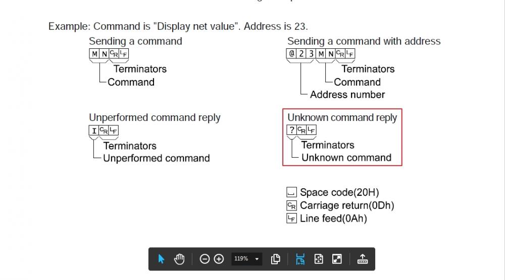
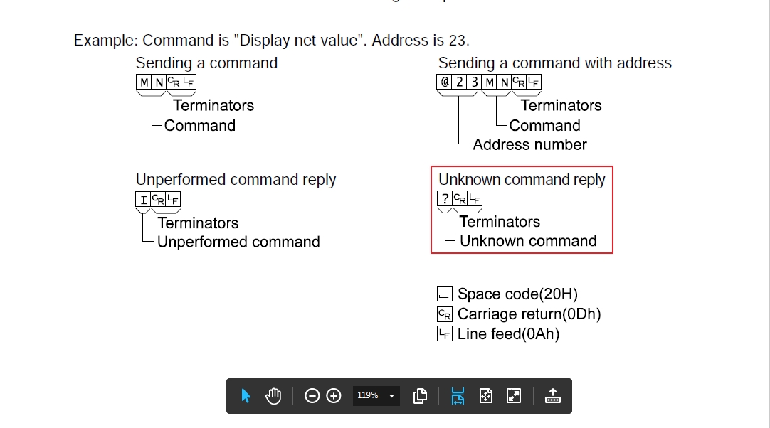
On 5/7/2019 at 10:48 AM, Wasan said:@riandanualdy There are "?" character because there are some unknown command response from weight indicator. You should check what is wrong about it. And you should try to remove <CR><LF> from send command (delete #0D0A) to send data again.
i Try just send RW without CrLf and the output is just weight data without ?.
And i think my problem its solved, Thank you for your help Mr. @Wasan and Mr @Michael Walsh.
-
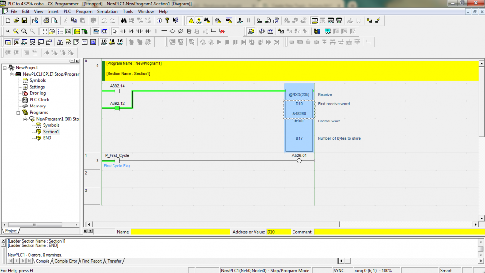
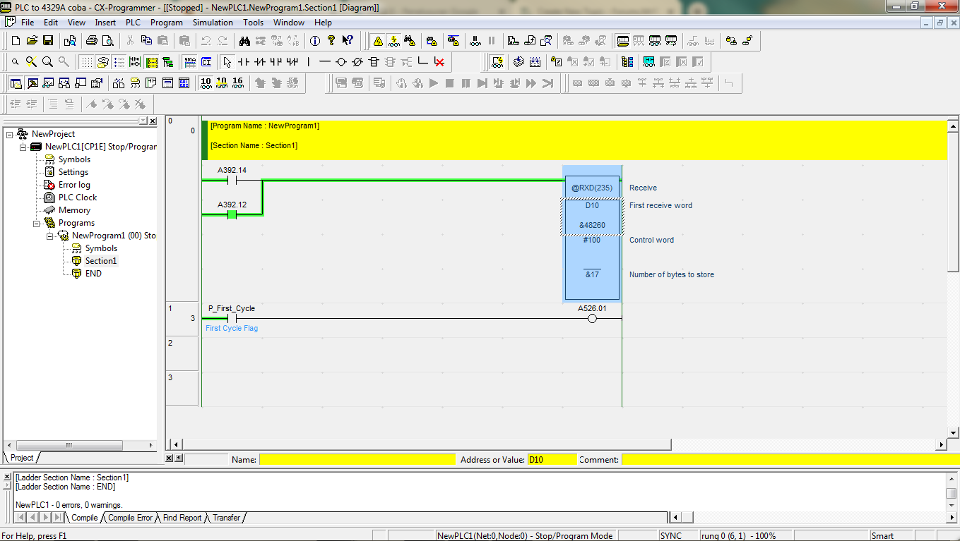
56 minutes ago, Wasan said:@riandanualdy You should connect weight transmitter with PC and check with serial communication software like hyperterminal to track how data are communicate. I think that A392.14 are On abnormally maybe there are something wrong with RXD data or loop back from other TXD data.
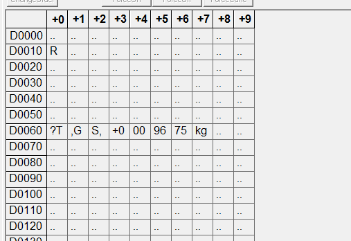
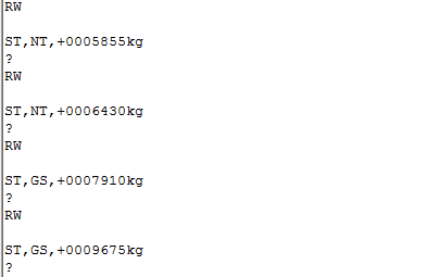
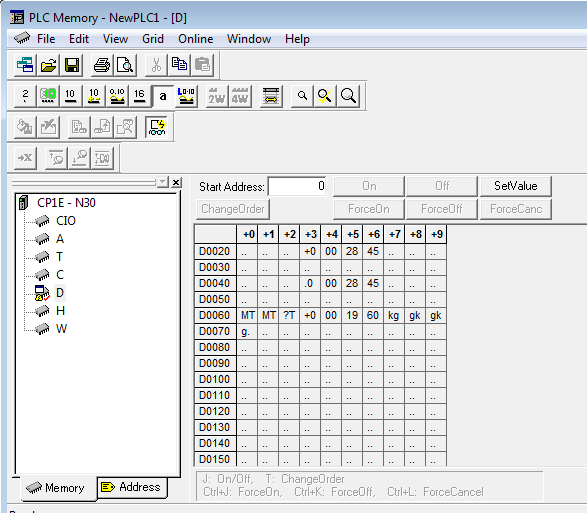
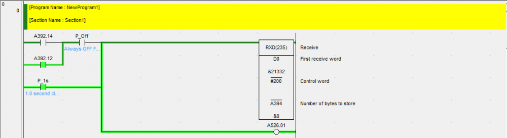
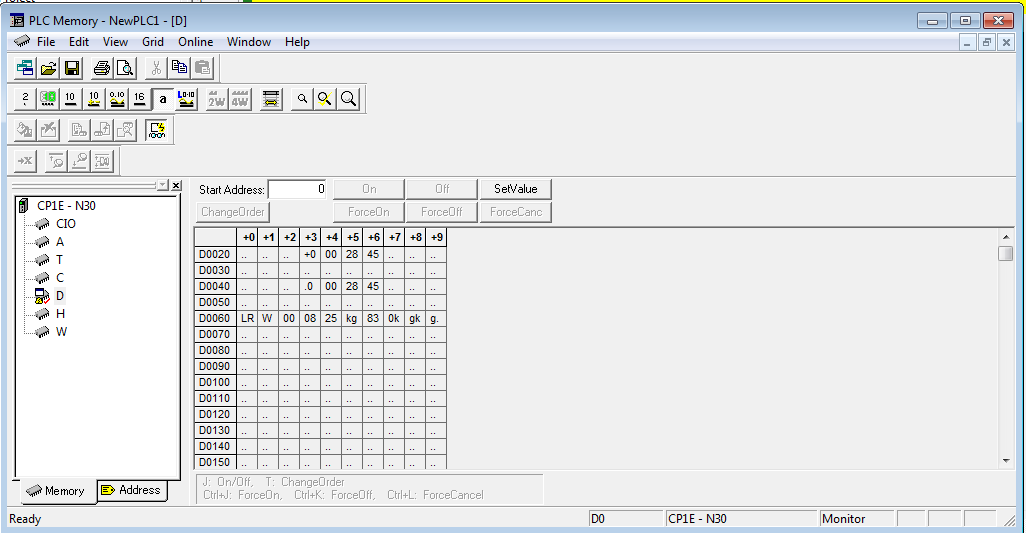
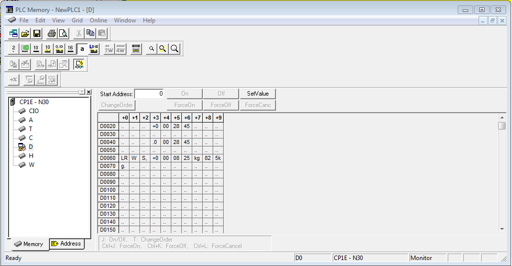
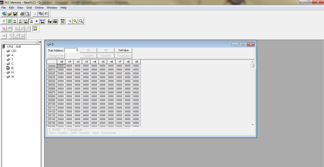
The post before this post i use ladder diagram V3, but if i use V2 and move it to my ladder diagram, the output is like this (check my image), first PLC get ST,GS,+0009675kg but after that the data change to ?T,GS,+0009675kg. I Attached the image for memory of PLC and i connect it from my weighing scale to PC and the second image is the output from PC
4329A TO CP1E TXD with command FIX.cxp
-
On 5/4/2019 at 1:29 PM, Wasan said:@riandanualdy you should clear data before recieve because format for each command are response not same.
LD@ are contact input with rising-edge check (Off to On) that will on for only 1 cycle time until input is off then on again.
Sorry, if i try again your ladder diagram, first the weight data is move to D60 and after that clear the data in D60, but if i change the position between RXD and BSET, just clear the data, not to get weight data.
1 person likes this -
21 hours ago, Wasan said:@riandanualdy Please check that you CP1W-CIF11 dip switch no.5 is not on because it means disable echo-back function when it turns on. Then I adjust you software to clear data from D60 to D69 before send data.
I try with your ladder diagram and its working. And actually if i use your ladder diagram and change SW 5 in CP1W-CIF11 to ON/OFF its not change anything.
My question is, Does all of serial communication(RS232 and RS485) With PLC (receive and transmit data) always must clear data memory before receive the data?
Can you explain to me what different between LD and @LD ?
-
3 minutes ago, Wasan said:@riandanualdy I think there are some data are echo-back at your CP1W-CIF11 maybe you should try to send other command that no data response (Zero, Tare etc.) and check that D register at RXD (I guess that you use D60) recieve data or not.
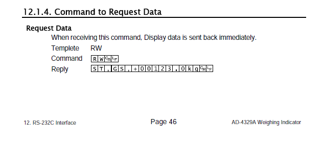
It's true if i send MTCrLf command, D60 is have data MTCrLf too but always move to D61. but i think its normal because if you read the manual book, if i send command MTCrLf the scale will send MTCrLf too to PLC, but why if i use command RWCrLf, the feedback is just not the weighing data but RWCrLF+weighing data. should i reset the port like RXD before?
-
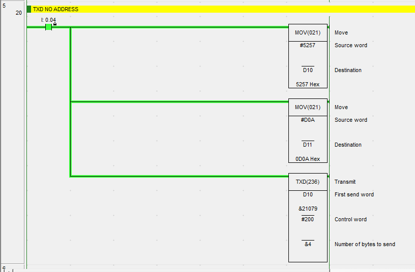
On 4/30/2019 at 9:41 AM, Wasan said:@riandanualdy First you should set D10 and D11 before TXD. For the last parameter of TXD you set at 2 bytes that means you send only "MT" (1 words or 1 D = 2 bytes = 2 Chars) If you need to send with <CR><LF> you should adjust to [TXD D10 #0200 &4]. If it is not correct maybe you should swap data to #544D and #0A0D.
I think i dont have a problem with command Zero and Tare, but if i use command RWCrLf to get weighing data the output is random not like stream mode or manual print mode, normally the output is ST,GS,+0000825 kg CrLf.
What should i do if i want to get the normally data?


-
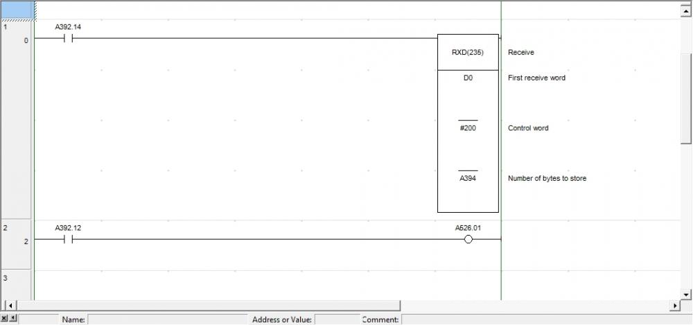
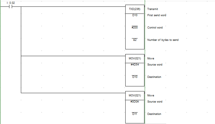
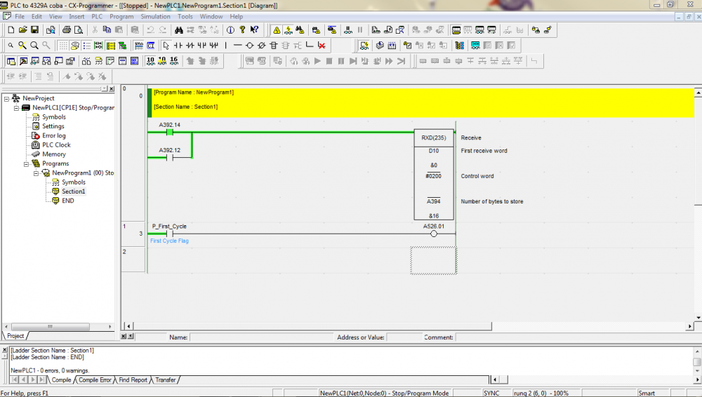
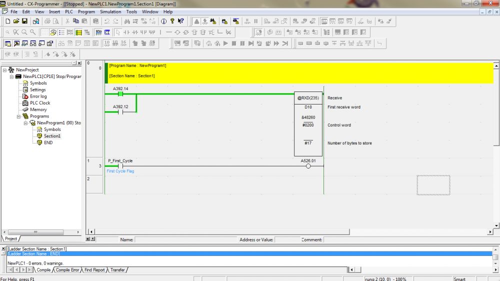
20 hours ago, Wasan said:@riandanualdy You should set A526.01 to On for reset Option Serial Port. Maybe you should use program like this.
For more information please check at this manual at page 242.
@Wasan @Michael Walsh yeah i done try your ladder diagram, and its working.
How about the TXD? if i use command mode and the example of command is MTCrLf or MZCrLf.
i done try to create ladder diagram, but i think its not working at all, but i think PLC done send data because if i change 0.02 to On the led in CP1W-CIF11 is blinking.
Thank you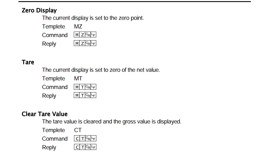
-
On 4/27/2019 at 0:12 AM, Wasan said:@riandanualdy Maybe you should restart communication port by set value to A526.01 after read data.
its working i think, i try use stream mode (send data repeatly) the memory can save data from weighing scale but sometimes A392.12 is ON and cant go off again,
And i read A392.12 description is ON when a communications error has occurred at the serial option port. The port must be restarted when this flag turns ON.
What is port address for me to restarted when A392.12 is ON?

-
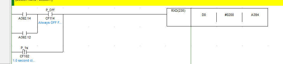
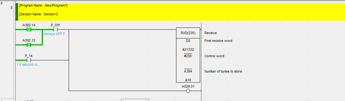
14 hours ago, Michael Walsh said:What is different is that the P_1s bit is a one-shot (differentiate UP). It is only on for one scan. Right click on the contact and choose differentiate up.
My thought is that using the P_1s bit will allow the code to clear out the buffer. For some reason, A392.14 is staying on, so the RXD instruction is only executed one time. There is clearly data in the buffer since A394 = 16, so the P_1s bit would empty out the buffer. Perhaps your device is sending multiple versions of the same string? See if there is a setting to have it only send one at a time. You could also connect this up to a PC with an RS232 adapter to look at it with a Hyperterminal like progam to see what your device is sending.
Mr. @Michael Walsh i think if i push print randomly with that ladder diagram, A392.12 is ON, A392.14 is OFF and must restart PLC again if want to send data (A392.14).
And if i use Stream Mode (Send Data Continously), i think can't use this ladder diagram.
any solution so i can compare the weight data (just number) like this picture and ladder diagram?
Thank you
-
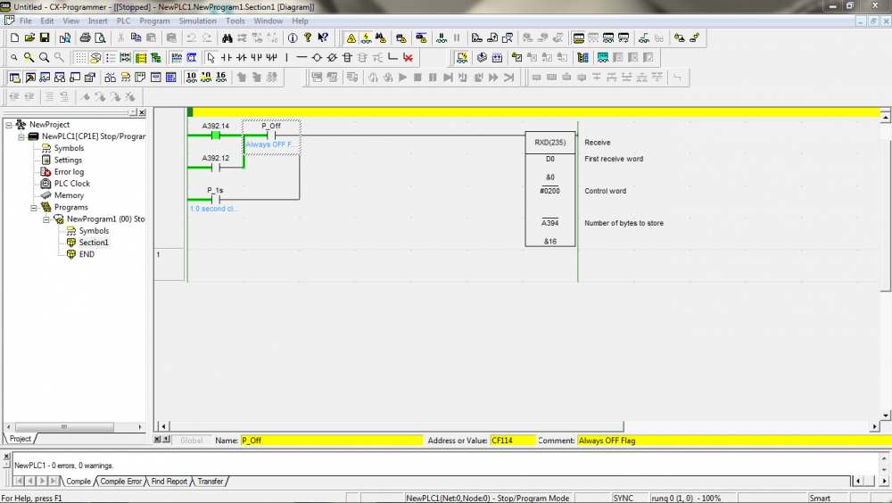
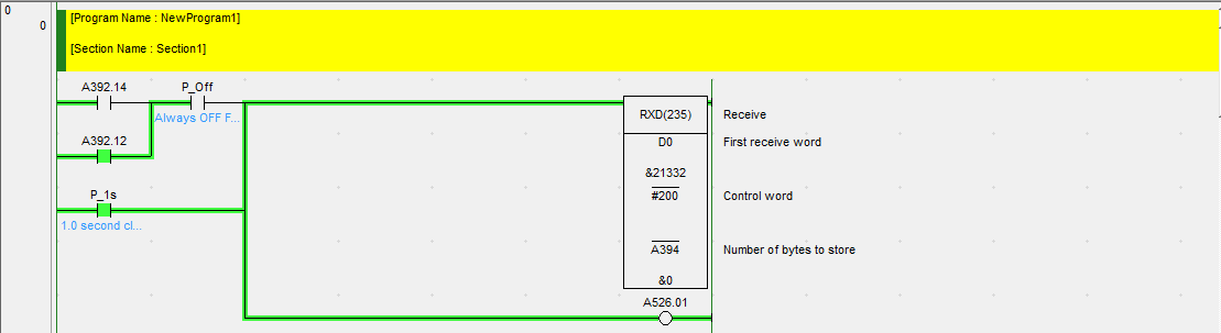
9 hours ago, Michael Walsh said:For testing purposes, change your ladder rung to this:
and let us know what happens.
Or, put a bit in place of the P_1s contact that you are not using elsewhere and turn it on manually when A394 = 16. Then check D10 (or D0 as I have done above).
Hello Mr Michael, I done checking D0 and data is same with AD4329a, but maybe sometimes if i push manually repeatly, A392.12 is on, A392.14 is off and can't get data and i think cant send data again after a392.12 is on.
but my question is what different with your ladder diagram and my ladder diagram before? can you explain to me?
-
50 minutes ago, Wasan said:@riandanualdy You should set dip switch 1 on CP1W-CIF11 to Off because you don't have terminate resistor at weigh sensor. Then you should use set F-47 value to be 1 for use RS-485.
i done change dip switch all of them is OFF and change F-47 to 1. and still cant get the data, just get from A394 is &16 and its true because total of data is 16 digit.
-
11 hours ago, Michael Walsh said:The manual that you attached for the AD4329 does not mention any ability to support RS485. It only shows RS232. Are you sure that it supports RS485? Are you using a converter between the AD4329 and the CP1E to change from RS232 to RS485?
This is manual book for RS485
-
48 minutes ago, Wasan said:@riandanualdy Maybe you should clear PLC memory and connect with weight module then push print button and check data again.
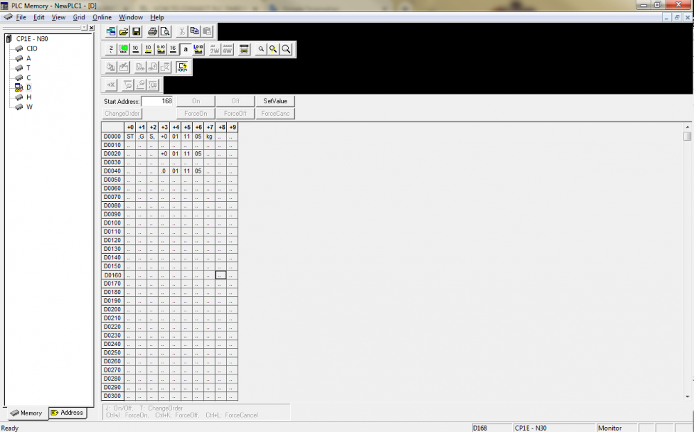
i done clear PLC memory and push print and check data again in D10 output still 00 but A394 is 16 and i think A394 is true because total data is 16,
-
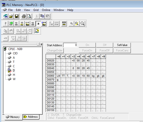
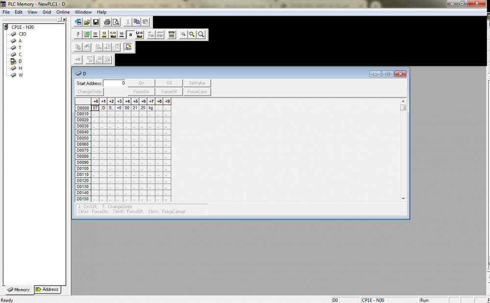
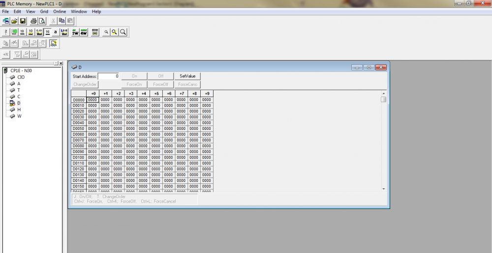
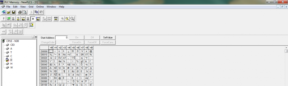
1 minute ago, Wasan said:@riandanualdy I have seen D10 have data value entry and complete flag A382.14 is on. You should monitor value at Memory on the left menu then check at D10 on text mode to monitor data.
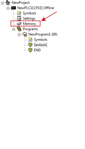
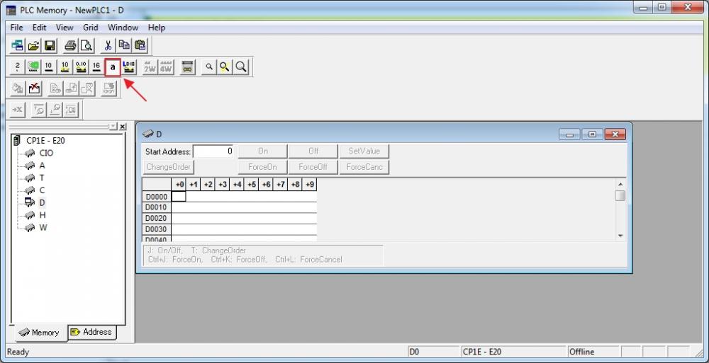
This is the memory D10. Actually the output from 4329A is ST,GS,+00001.3 kg (example).
-
1 hour ago, Wasan said:@riandanualdy I think you use stream mode If you have USB to RS-485 converter you should connect with weigh scale then press print button and check that data are out to hyperterminal (or similar software) or not. If not maybe you should use commnication command mode (F41 = 3).
I use 4 cable,
CP1W 4329A
RDA SDB
RDB SDA
SDA RDA
SDB RDB
and i attach the screenshot of cx programmer
but still i cant get the data from weighing scale if i push print (Manual Print Mode).
-
On 4/20/2019 at 3:16 PM, Wasan said:@riandanualdy Maybe you need to adjust DIP switch on CP1W-CIF11 in pin 2 and 3 to on for use RS-485 2 wire.
Sure i done adjust DIP switch pin 1,2,3 ON and 4,5,6 OFF, but still cant get the data.
Is that the setting of PLC Settings and ladder diagram is true? because im not sure about that.
-
Hallo, i want to connect Omron PLC CP1E use CP1W-CIF11 to AD4329A with RS485 communication.
my wiring is
CP1w-CIF11 AD4329A
SDA- SDA & RDA
SDB- SDB & RDB
and until now, i cant get data from AD4329A. Do you have any clue for this project?
Thank you
Riandanu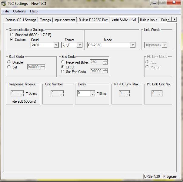
-
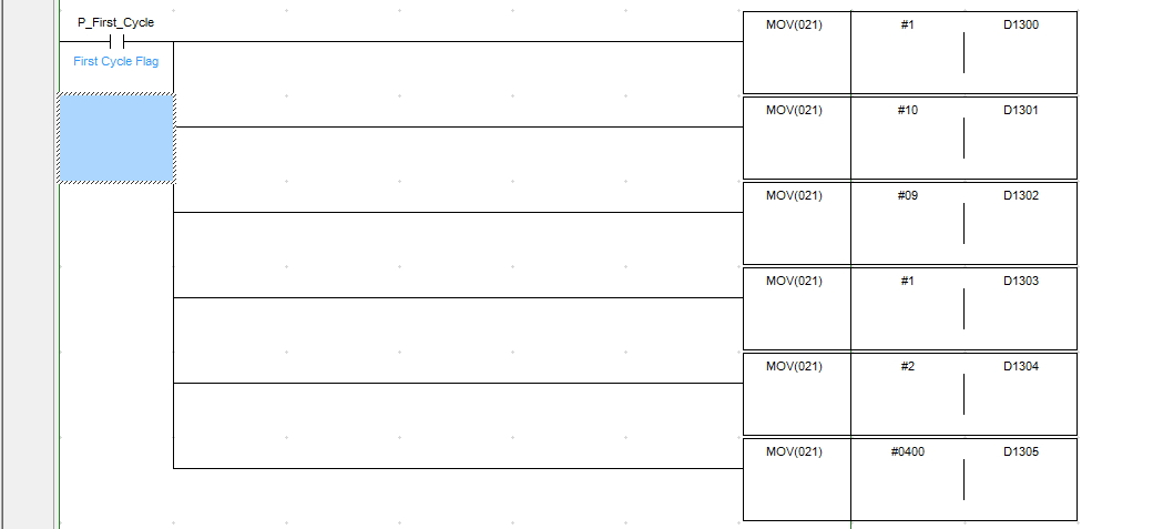
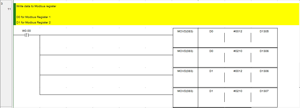
12 minutes ago, Wasan said:This is example for writing Modbus registers for 2 register at start address 40001 for more information please check link below at page 245 - 253.
This is short instructions
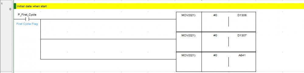
1. Initial data when power on.
2. Config Modbus parameter.
D1300 -> Slave Address
D1301 -> Function Code
D1302 -> Communication Data Bytes
D1303 -> Start Address
D1304 -> Number of registers written
D1305 -> Number of Bytes to send data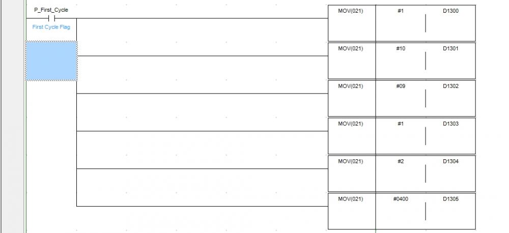
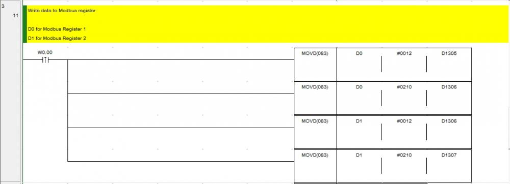
3. Config data to written on Modbus register use MOVD because data is in lower byte of D1305 and upper byte in D1306 and other too.
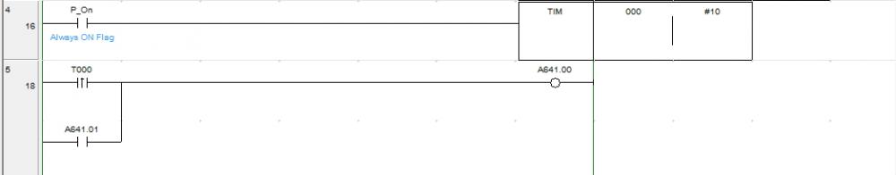
4. Modbus communication trigger.
Finally i can create write multiple register, i just follow the pdf you give me.
I want ask, how to read data (read input register and read holding register) real time or in data memory always display the real time data?
-
On 10/20/2018 at 10:01 AM, Wasan said:I have checked AD4402 manual it have not information about modbus code but you can check it by connect USB to RS-485 on your computer and use this software to test Write multiple registers (function code 16)
I done test with modbus master, and if i use function code (0x10), i can do write and read the register at the same time.
how about the ladder diagram?
-
2 hours ago, Wasan said:I have checked AD4402 manual it have not information about modbus code but you can check it by connect USB to RS-485 on your computer and use this software to test Write multiple registers (function code 16)
okay i will test it with software, i will tell you about progress later
-
11 minutes ago, Wasan said:First you should check that your slave device could receive modbus command 16(10 hex) or not. If it could you should use easy modbus to write them by set Function code to 10(hex) and set number to send byte for example please check thsi link at page 161
How to check my slave device can receive modbus command 16(10 Hex)? i use CP1E
-
Hallo my name is Danu, i have a CP1E wirh CP1W-CIF11 and connect to modbus RTU device, i have done with write single coil, write single register, read single register and read multiple register. But i try to write multiple register, the indicator of CP1W-CIF11 is off and if i check d memory its no data. I attached my cx programmer.
Can you help me create write multiple register in cx programmer?Thank you


NB DESIGNER Number Input
in Other Omron Software
Posted
Hello,
I done connect HMI NB7W series to PLC CP1E and just using input and output (0,0 and 100,00) and i can send data from weighing scale to PLC CP1E with RS232 communication.
My Question is, if i want to send data from HMI NB7W to PLC CP1E but must input the new data first using number input in HMI NB7W, can i send a new data with RS232 communication (like send data from weighing scale to PLC CP1E)? so i can save the new data to memory in CP1E.
I use NB Designer Software and CX Programmer software.
If possible, can you tell me how to do it?
Thank you
Riandanu