

collinsd70
MrPLC Member-
Content count
264 -
Joined
-
Last visited
Posts posted by collinsd70
-
-
On 5/2/2020 at 10:15 AM, koelkommer said:Good Morning everyone!
I have an existing Profibus network which is used for monitoring only, it has a Mitsubishi Q series Profibus master and 7 slaves, works perfectly. I want to add 2 x Danfoss FC102 drives to the network (also for monitoring only). I have downloaded the Danfoss GSD files and installed those using GX configurator now I need to either find some already made Function Blocks to go into GX IEC Developer or I have to make them myself. I have not done the latter before but can be quite a quick learner given time. Has anyone here done this before? Maybe someone could steer me in the right direction.
Thanking you all in advance and be safe stay at home if possible (away from the virus).
Hi koelkommer.
So you have added the 2 nodes your profibus configuration- good.
You need to save your configuration and download to the PLC.
From memory- these GSD files have different "PPO Types". I think before I used "PPO Type 3". This provided x2 16-bit variable outputs. I think there was also x2 input 16bit variables which had the status bits inside.
All I then had to do was write the commanded speed into the second Data register (16 bit). It should be as simple as that.
Here I attach the links to Danfoss resources.
Let us know if you need any further info.
https://www.danfoss.com/en-gb/products/ac-drives/dds/vlt-hvac-drive-fc-102/#tab-documents
Profibus addresses can be defined via dipswitches or via inverter paramaters.
Regards
Daniel
It was as simple as that.
-
On 2/20/2020 at 4:43 PM, Gatzrulz said:Hi,
Is it possible to have two hardware configurations which can be switched through HMI. currently i have two hardware configurations and the project remains same. So without connecting with Simatic Manager i want to switch the hardware configuration.
I believe the answer to this to be a no....
However you have 2 possibilities here: -
1. Create 2 SIMATIC Projects, load the respective project into the PLC as and when you need to
2. Create your Project with all relevant nodes (so compile your project with a full list of hardware)- you can then use System Function SFC12 to "disable" individual nodes, then you can "enable" them later when required. Using this method will stop the CPU calling a fault OB and moving the PLC to stop mode.
Let me know what you think.
Regards
Daniel
-
On 10/30/2019 at 9:50 AM, gowthamsudherson said:Dear Experts,
I want a sample block to find out the status of my Profinet cable w.r.t Hardware configuration.
whether the cable is connected or disconnected from the node.
Either my nodes may be VFD, HMI, SCALANCE, etc...
please share the sample blocks...
S/W ===== >Tia portal v14 sp1 update 6
H/W ===== >CPU 1214C DC/DC/RLY
hanks in advance
Hi there.
Please see attached link.
Regards
Daniel.
-
On 10/30/2019 at 3:03 AM, GERRY JERESANO said:Hello.
I am new at Siemens Plc. My problem is after power interruption my S7 300 alarm BF 2 and BF 3 blinking And SF too. I reset the entire system but still BF2 and 3 still on blinking.
What should i do. ?
Thank you.
It sounds like you have a disruption to atleast 2 of your networks (or not configured).
Check your Diagnostic Buffer for further information
Regards
Daniel.
-
Hi Sango.
Are you writing to defined I/Q addresses?
From what I can see in your Diagnostic Buffer, you are experiencing IO Access errors, can you post your HWConfig? for the 2 IM151 modules and their respective devices.
Also remove the Calls in OB1, reset your CPU and check all diagnostic lamps go out (BF1, SF on CPU and LED on ET200). Let me know what happens
Regards
Daniel
-
-
On 1/9/2020 at 2:17 PM, dunc said:i have been dumped an unfinished project with no budget left and i have been tasked to find a way to connect a new Siemens PCS7 system with profinet to 2-3 existing A-series mitsubishi systems.
we have limited I/O availability on the mitsubishi side, so i dont think an old school direct multicore connection is going to be viable.
the A series is connected to a SCADA system, so an OPC is an option, but turning the SCADA PC off would then stop the new process.
what options can people suggest that isnt going to require buying discontinued parts off ebay?
Hi Dunc.
In terms of hardware- you have a few options (again, I know this hardware is obsolete but is readily available cheap and reliable).
The A-Series does support Profibus-DP via the A1SJ71PB92D module, this allows cyclic communication as a slave or master (Profimap or DP Configurator is needed if you plan on running as a master).
On the Siemens side- you could simply use another 300 CPU (for example S7-317 2PN/DP). This way you can convert Profibus DP to Profinet IO
Please be aware the A-Series Hardware only support a tranfer rate of 32BYTES, however in Mode E you can get another 32BYTES (so 64BYTES in total).
If you want further help in setting this up or picking the hardware, feel free to let me know, maybe provide more information on the amount and types of data you want to transmit.
A Series 1 (Profibus) <---------> (Profibus) S7-300 CPU (Profinet) <----------> (Profinet) PCS7 System
A Series 2 (Profibus)
A Series 3 (Profibus)
Regards
Daniel.
-
11 hours ago, Blackd50 said:Looking for a copy of software.
Thanks
You should contact your local Mitsubishi Electric vendor.
Regards
Daniel
-
Hi gerdam.
Welcome to the forum, what is your communication method? Could it be that the path you are trying to use has been reset to default addresses and settings due to the low battery fault?
Try connecting directly using the Modbus or Modbus Plus port....
Regards
Daniel
-
4 hours ago, Blackd50 said:Trying to figure out how to read the configuration imagine file .dpi ? I am using GX Configurator-DP 7.12N with GX Works2. I am trying
to upload the configuration from the Profibus module QJ71PB92V, the only upload I can find is the configuration imagine upload. But I have
no idea how to open it and very the configuration settings of the module!
Hi Blackd50.
Firstly, welcome to the forum. If memory serves me correctly- the file you should be working with is a .dp2 file.
Please clarify- so you need to "upload"? (from the PB92V) or download (.dp2 file to PB92V), either way- you need to set the initial head address and communication path in order to exchange any level of information in the Configurator-DP software.
Regards
Daniel
-
Ricardo.
You should start a new thread for this or use the search functions.
See here: http://www.plctalk.net/qanda/showthread.php?t=107389
You can also "upload" EDS file via RSLinx Classic, otherwise you can set up the module with "Generic Ethernet Module" and use the instances attached inside the link.
Otherwise it should come in the attached CD-ROM included with the sale of the Robot.
Regards
Daniel
-
Hi Emre64.
As others will also tell you- discussing methods to find or circumvent passwords is against the rules of this forum.
May I suggest you contact your machine distributor to discover the password the legitimate way.
Regards
Daniel.
-
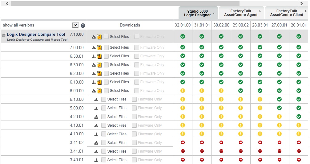
Hi necat.
Firstly, welcome to the forum.
From memory- I had this before; and I fixed it by simply upgrading the cmpare tool.
What version are you using? The most recent version is v7.10.00
Regards
Daniel

-
Hi fLaXx.
Firstly welcome to the forum.
Yes this is totally possible. If you go online with your "earlier version", inside the block container you will see small green/ orange circles- this tells us that the blocks are inconsistent (ie the block in the PLC is different to the offline project). You can simply then right-click on the block and click "upload from device". Once all your blocks are green- your program is consistent.
Regards
Daniel.
-
23 minutes ago, Ron_S said:Thank you for that.
They are supplying the reader so I don't know what type yet.
But at least with that information I can cobble a price together
Thanks again.
Once you know the reader model/ make....come back to us and we can have a closer look at what needs to be done.
Regards
Daniel
1 person likes this -
17 hours ago, TYUNTTURTUTUTYTYU said:Hello sir
How to download omron scada
You should speak to your local distruibutor here...
1 person likes this -
12 hours ago, Ron_S said:I've been asked to beat a quote for a conveyor system
That part is no problem.
They want to use a barcode reader to decide which channel or which conveyor route the product will take into the warehouse when the barcode is read.
Now I have never programmed or used a barcode reader in my programs before.
I don't even know what add on I will need on an Fx3.
I will need to take data from it and decide which of four routes it will take.
There is no hmi, just a plc.
Any preliminary advice or hints well help at this time.
Thanks
HI Ron.
Cant say ive used the FX for Barcode Reading- but have some good Mitsubishi experience.
I have used the Keyence SR1000 Barcode Reader before on a CompactLogix system which was very easy to set up and work.
The nice thing about the SR1000 is that it supports so many protocols (PROFINET, Ethernet/IP etc) but can also be wired via RS232.
Anyways- having a quick google reveals a lot of examples of people using other Products and Programming Languages. This examples shows an example via Ethernet on the Q-Series Platform (the FX should be able to do something similar with an Ethernet Connection).
http://dl.mitsubishielectric.com/dl/fa/document/manual/sol/sensor/sh081577eng/sh081577enga.pdf
Either way- let us know if you need any further information.
Regards
Daniel.
-
Hi ABlearner.
Welcome to the forum.
The first thing to check is the Motion Error code housed inside your Motion Instruction.
Open your tag structure after the ER has occurred and navigate to yourMSOtag.ERR and feedback the error code....
Regards
Daniel.
-
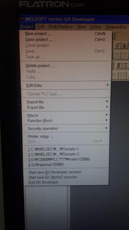
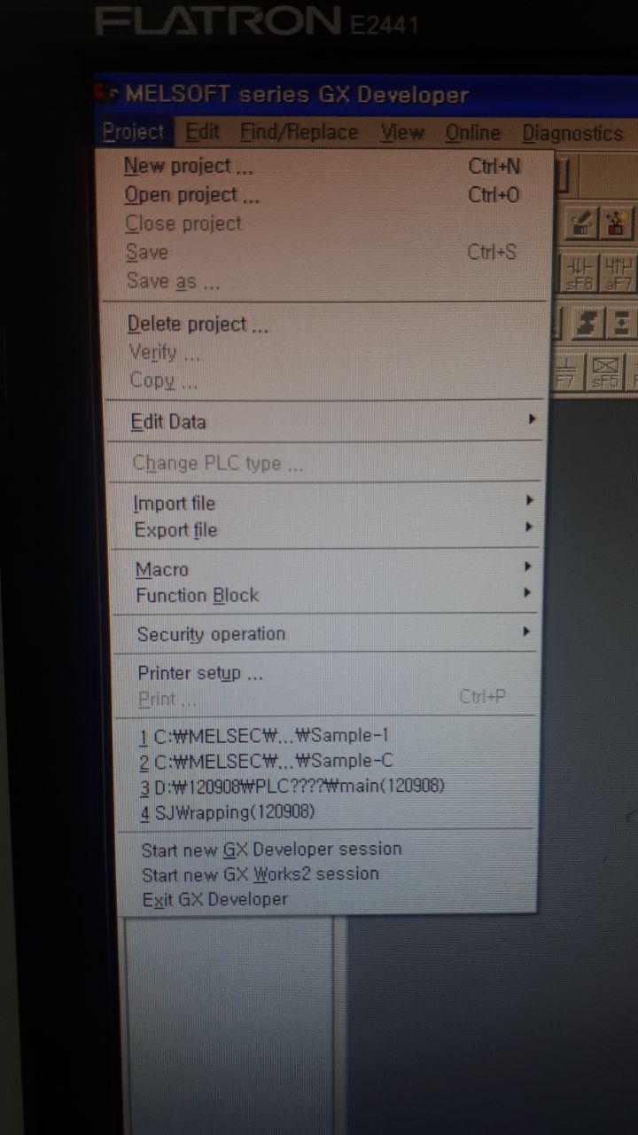
56 minutes ago, kurdapyu said:thank you everyone for your response.
i think i am opening the right file. because once i click the project button, there are portion for recently open program.
and when i click the file/program. it display the error "Failed to read the project file" as shown in the first photo.
Thanks again.
Please upload your program and I will check for you....
Regards
Daniel
1 person likes this -
6 hours ago, carlosvillela said:I'm trying to connect a anybus ethernet/ip scanner with an allen bradley model 1794 AENT/B, but i can't find the assembly instances and data size. Can anybody help me please? I had already try to look everywhere.
Found this document on the HMS Anybus Webiste- it talks about the instance/ structure sizes for an ethernet/ip scanner. Is this what you need?
You may be able to find a tag structure or UDT also on that page that you can load into your Taglist.
Regards
Daniel.
-
55 minutes ago, melad said:Dear all ,
I have PLC M7 486 and connected encoder on EXM card 478 on the same rack
I need to know encoder address on PLC
programmer was written in C language
You will need to study the hardwares structure and programming syntax.
Without your program- this is near impossible to figure out.
Regards
Daniel
-
If you are opening this directly from windows explorer...make sure you are opening the right file (from memory there are a .gpx and a .gpxx file) this error normally happens when you open the wrong one.
Alternativley upload your program and I can check for you.
Regards
Daniel
-
Hi Dunc.
Sounds like very odd behavior to me, maybe try a standard ROM format? then reload the program?
Make sure if you are using retentive memory- that you backup the device registers.
Regards
Daniel
-
11 hours ago, pappaleif said:Hi all,
At my work, we are unfortunately still using GX IEC Developer 7.04. All of a sudden I can no longer open any project at all with my GX IEC Developer. I can start the program just fine, but as soon as I choose a project to open I get "cannot initialize communication manager". And after this, I get another 2 "cannot restore parameter file. param.tmp not found" and "cannot restore transfer setup file! cnct.tmp not found!". Doesn't matter which project. And I have opened these earlier with no problem for years.
I have tried reinstalling ALL Mitsubishi software on my PC. And restarting PC.I can't find a link to any other changes I have done on my PC either...
Does anyone have any idea how to solve this?
Best
Hi pappaleif.
Sorry, cant say ive ever seen this error (ive used this software for 5-6 years). All I can think is maybe there is a conflict with Windows or something (maybe try a system restore?)
Otherwise the only other option you have is to run GX IEC in a Virtual Machine (I run all my software in VM's for these exact reasons).
Regards
Daniel.
E71 Read Only?
in Mitsubishi
Posted
Hi Colin,
What Mitsubishi software are you using?
From memory- the early versions of the Mitsubishi Software (GX Developer/ IEC Developer) don't have read and write controls.
You may be able to configure read-only access on the SCADA system.