

Muhammad Azeem
MrPLC Member-
Content count
11 -
Joined
-
Last visited
Posts posted by Muhammad Azeem
-
-
Hi,
I am writing some routines to decode the data from my Input: data array to User-defined Array Parameters. Is that possible to have a generic routine to decode data coming from more than one module?
I have two Module ENode and ENode_1. I have defined User-Defined parameters for the module. Can I make a generic routine to decode the data coming from these two modules and put them in the defined arrays?
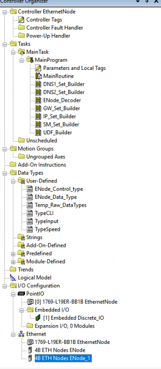

the two arrays ENodeData[0] and ENodeData[1] have the Generic User-Defined parameters.
-
Just now, PLCMentor.com said:Yeah I never could figure out what the purpose was behind this and never saw any real answers to the questions being asked so I just threw in the towel.
LOLxxxx,,,, Thanks for your towel..!!! Actually, I am new to PLC after the senior employee left the work. I am just getting there, to be honest......
-
Just now, pcmccartney1 said:I still don't think I understand what you are trying to accomplish.
What is the L19ER talking to or with and exchanging data?
Where did you get the "Module-Defined" data types? Even if you where using the "Module-Defined" datatypes, you would need to define the module in the I/O Configuration. It would then reference the "Module-Defined" data type and create the tags in the database, rather than you simply adding the ENode_1 in the controller tags.
I have managed to do what I supposed to. The number of bytes were 251 and make them INT I changed them 252 bytes. Thanks for your support.
-
Please find the attached image for Ethernet Interface.
the tags are in module defined tags.

-
Anybody..?
-
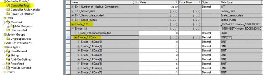
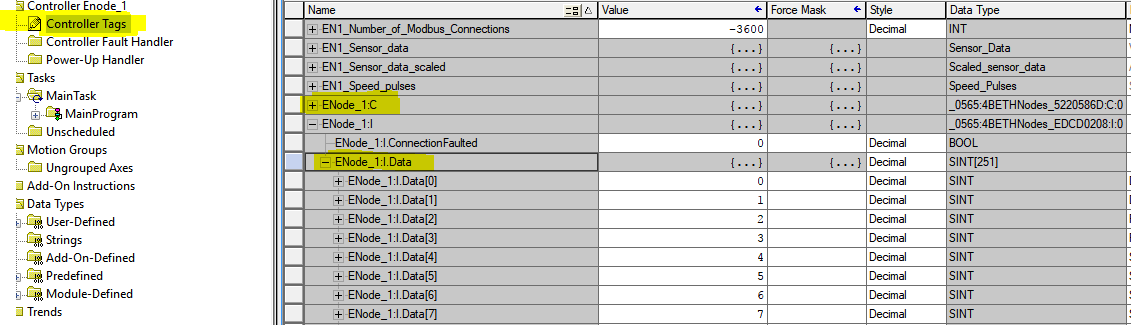
Please find attached the image. As you can see in my EDS file I have defined 3 Assemblies and you can see two of them in this attached image. The parameters section I have added in the EDS file is to make the ENode_1:I:Data to make INT and read those tags from the EDS file. I can import the Parameters tags in the ENode_1: C but why not in Input data tags.
-
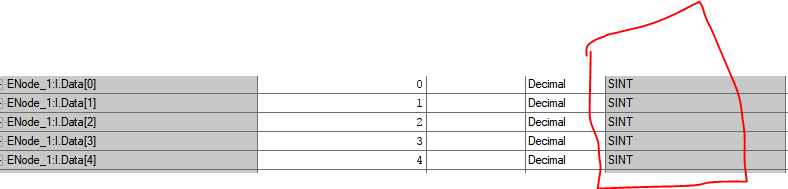
This is the EDS file I have created so far. the thing I want to achieve is for example, on my device I have 2 bytes Datatype. Let's assume I have a temperature field on two bytes 0X000A, but in the Logix Designer in the Controller tags, this value comes like SINT, 00 in one index and 0A in another index. I want my Input tags in INT format so a user can see 0x000A as a whole without decoding the data.
-
The data values I have are based on INT (2 Bytes) and the input tags are SINT (1 Byte). I just want the customer to install the EDS file and find the data rather than decoding it.
Please find attached my EDS file in which I have defined parameters but unfortunately unable to import those parameters in RS Logix. Designer
-
Hi,
Is that possible to define INT data type in EDS file so the Tags for the module in RS Logix Designer would receive INT data type in Input Tags not SINT?
As marked in the image, the Logix Designer is receiving data as SINT but I want to have INT data type.
Thanks
Muhammad Azeem
-
Hi,
I am working on a project in Digi Module ConnectME9210 and sending data to Allen Bradley PLC (CompactLogix 5370 family). I am not sure which endian I should use to send data. Does Allen Bradley receive Data in Big Endian or Little Endian?
I have another question as well. Can I make an EDS file to tell the PLC to receive data in UINT16, not as a single byte?
Muhammad Azeem


Generic Routine to Decode data for one than one Module
in Allen Bradley / Rockwell Automation
Posted · Edited by Muhammad Azeem
Thanks, VDS and Gerry. I have managed to do that. I am a newbie in PLC development.
Cheers.