

pop29684
MrPLC Member-
Content count
124 -
Joined
-
Last visited
Posts posted by pop29684
-
-
Has anyone implemented ProfiSafe over TwinSAFE? Would you recommend it? What obstacles or quirks did you need to resolve? Would you do it again?
-
What is the purpose of having a PLC CPU on a mobile rack?
Will the envisioned mobile PLC also have I/O attached to it via a hardware rack on the mobile cart?
Will the envisioned mobile PLC be connected to any remote I/O via the bridged network (I/O mounted in a stationary remote location?
Is the plant network secure - is it isolated from any connection to the outside internet?
What is the intended wireless connection to this envisioned mobile PLC - a machine, a PC, etc.?
-
You can get a Codesys license for Raspberry Pi. Last I checked it ran around $125 USD.
-
On 9/10/2021 at 9:47 AM, Crossbow said:You do not need the AND on the second timer, because the moment TON_2 finishes, TON_1 becomes false and that would reset both timers. Putting it on TON_2 is redundant.
I think I may have been misunderstood. I was not ANDing the two timers. Allow me to rephrase: Do not modify the existing time logic of either timer (TON_1, TON_2).
On 9/10/2021 at 9:47 AM, Crossbow said:It's an IEC software, so the TON instruction always counts up. And I am not sure you are allowed to write to the current value.
You may be correct. I was thinking of the Siemens platform where the TON instance DB is accessible.
-
Do not modify the existing time logic of TON_1 and TON_2. Instead, when BOOL_tag state goes to "1" then move the final value of TON_1 into the active timing register of TON_1. This would be "0" if TON_1 counts from preset value to zero; this might be "100" if TON_1 counts from zero to preset value. You need to verify the operation and final value of TON_1 in order to realize what is the final value of TON_1.
1 person likes this -
Try performing a "compile hardware & software". If differences still exist you will need to perform a full compare (not the quick compare). De-select all filters then begin re-selecting the filters one by one until the difference returns.
-
Where do you plan to do most of your work? As a general rule of thumb, ladder logic is the most common here in the United States. But if you're interested in working in the European market then perhaps function block diagram or structured text would be the better choice.
-
Perhaps a good application for a simple heartbeat bit? If the bit isn't seen, track the length of time it is missing. Probably not accurate down to the second but might be worthwhile.
-
I'm afraid I don't have any answers for those questions. I have never used the encoders you are referencing. I hope someone else on this site would kindly supply an answer.
-
Have you contacted Heidenhain? Here's a link from StartPage to a PDF: https://www.heidenhain.be/fileadmin/pdb/media/img/587718_08_A_02_Drehgeber_fuer_Aufzugsindustrie_en_01.pdf. I think you might find your answer (or at least get a direction) from page four. Perhaps the ECN 113? Note the shaft differences between it and the model you currently have!
-
On 12/9/2020 at 0:14 AM, Kiiza said:The calculated result is just a DWord. The Dword has 4 bytes (2 words). When I check the DWord, I see all the 4 bytes contain information. And the information in the 4 bytes is not necessarily the same.
I understand the structure of the DWord very well. What I don't understand is why the SCL code (which has not been posted) is generating data in all four bytes of the DWord. A single integer converted to a 7-segment map by the SEG instruction only requires one byte of data - not four. I am suspicious of the SCL code.
Your STL and SCL conversions are not necessary. I explained that in my very first reply:
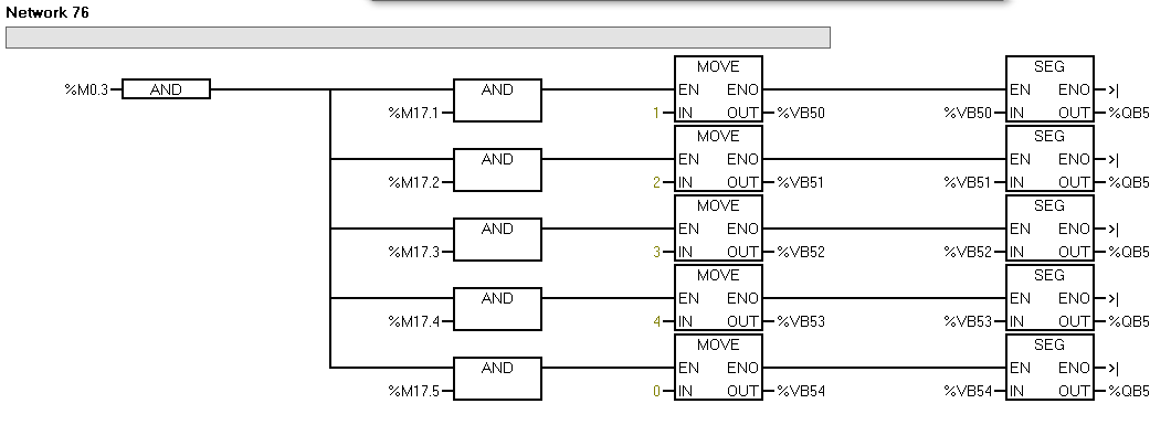
On 6/17/2019 at 5:59 PM, pop29684 said:The S7-200 manual (p325) shows the relationship between the integer value to be displayed and the corresponding segments that must be ON for the correct value to be seen on the 7-segment display. The 7 segments are ordered from "a" to "-", with segment "a" being the LSB of the byte and "-" being the MSB of the byte.
If you study the S7-200 manual (p325) you will be able to see how the 7-segment display is mapped into a byte value. I gave you the 7-segment map values (6, 91, 79, 54) for the digits (1, 2, 3, 4, 0 respectively) from the code you posted. If you need to map other digits (5, 6, 7, 8, 9) then use the information provided in the manual to do this. You will also need to develop logic that will turn those additional integers on and off. That is the function of the markers M17.0 - M17.4. Additional digits will require additional markers.
There is no problem using the STL/SCL code other than it reduces the efficiency of your code because it introduces something that is entirely unnecessary.
Compare this:
On 6/10/2019 at 2:08 AM, Kiiza said: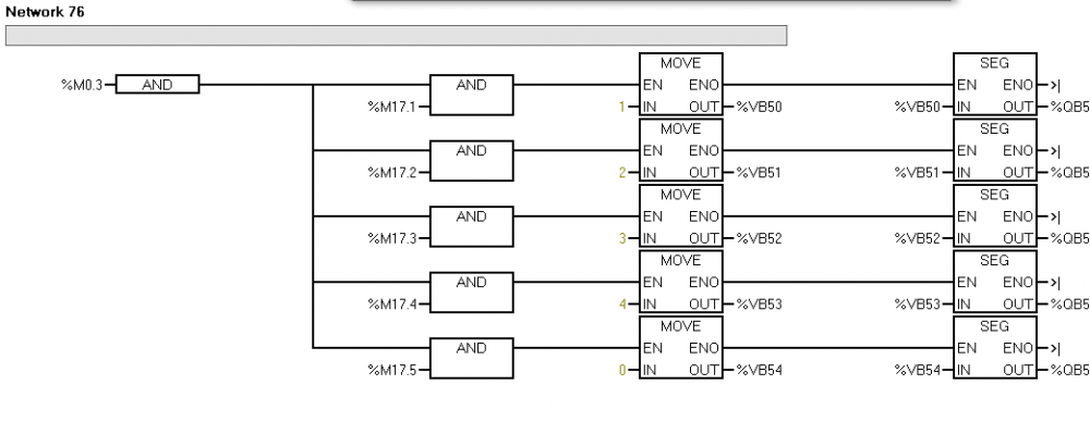
with this:
On 6/17/2019 at 5:59 PM, pop29684 said: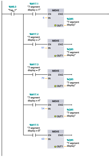
The efficiency is immediately obvious. The need for VB50 - VB54 is eliminated. The need for the repetitive call of the SEG instruction is eliminated.
True, the SEG instruction will conveniently convert a digit on the fly to a segment map but at the expense of, arguably insignificant, longer scan times and more memory usage. Manually mapping the segment values will reap the benefit of using less code, having less module calls - all of which translates to saving a little scan time and memory. But perhaps this is not important in the project with which you are working. Or perhaps you are determined to understand the operation of the STL/SCL code. Or maybe you want to build your own SEG module that, when called, takes the single digit integer and gives the appropriate 7-segment map value.
As far as the DWord contents, if you know the 7-segment map value that you expect in the byte, then it is a simple matter to compare that value to the values in the four bytes of the DWord. Then you know exactly which byte contains the data you need.
Good luck, my friend!
-
Why would there be any data in the other three bytes? The logic only requires one byte to hold the necessary segment map, correct? Is your calculated result being expressed as a signed integer in a DWord?
-
Is your output variable addressed as a double word (DWord)? If so, perhaps it should be addressed as a word or even a byte. If not, you may need to convert from a DWord data type to a Byte data type. That discussion is on p109 of the Siemens S7-1200 Easy Book (found here: https://euroec.by/assets/files/siemens/s71200_easy_book_en-US_en-US.pdf).
-
Thought I'd share an experience I had earlier today working on a (limited memory) L61 Rockwell processor. I knew there was very little room left in the memory but needed to add some functionality and decided to give it a try anyway. I couldn't take the machine down to make a download so made a number of online edits, successfully accepting and finalizing after each edit. Got down to the last four edits which required zeroing a tag of type REAL. The instructions were on four separate rungs. Hoping to save time (and all previous edits were successful), I added the four MOV instructions (MOV 0 into TAG) and pressed the "finalize" button. I was caught quite off-guard when the process failed: insufficient memory. AAAAGGGGHHHH!!!! So close! I tried to remove some logic to free enough memory to add the required instructions. Nope. Rockwell was not going to negotiate. That left me in a position where I thought I was going to have to take the machine down and do, hopefully, a download that would push the processor memory to the limit but be accepted without any hiccups. But before I did that I had a fortuitous thought. I F1'd the MOV instruction and hoped to find a complete explanation of the instruction, including timing diagrams, execution time, memory requirements, etc. Oh wait - that's Siemens. GROAN. Curious and desperate, I replaced each MOV instruction in my edited code (I'd estimate somewhere around 20 instances or slightly more) with the CLR instruction - including the four additional instances I needed. And finalized the edits with bated breath. To my utter surprise (again!) the edits were finalized without overrunning the memory. A MOV instruction requires memory for both the source and destination. Since I was only clearing a memory I didn't need to reserve memory for the source. Using a CLR instruction implies "0" (zero) for the source but requires no memory for the source value. Hence the efficiency. Obviously, this story would have a different ending if I had been trying to move some value other than zero into a destination tag.
I offer my experience as a lesson if you ever need to streamline some code to fit existing memory space.
I also would like to know if there are any downsides to what I've done. Have i overlooked any potential pitfalls? Thanks in advance for the advice.
-
Thanks, Bob.
-
I have an existing machine that pulls several rolls of film through it and executes a sealing process. The machine has a scaled feedback value (Tag: Velocity, Type: REAL). No one knows for sure what the engineering unit is (inches per second, feet per minute, etc.) of this tag. The supervisor wants to add an accumulative length counter based on this feedback value. The purpose is to have some idea of the total amount of film run through the machine for comparing to the total pieces of product produced. A colleague suggested using the TOT (Totalizer) function block or structured text instruction in a timed task. But the instruction itself has a timebase for execution control. I've searched the forum but cannot find anything related. Anyone have experience doing this or something similar? Or perhaps use a different instruction? The processor is a CompactLogix 5730-L18ERM. I just received the project specifications today and the due date is next week. (Of course!) So there is no time to research, design, purchase, install additional hardware. No pressure here! Haha.
-
From the RS Automation.biz website: This model is discontinued, so please contact Customer Center (1588-5298) for further information.
However, if you will go to their "Data" page you will find their customer support, including manuals, software, etc. I downloaded the software .zip file for free.
P.S.: the software might be named something other than winfpst.
-
Joe, I've also run into these situations. In most of them the logic aggregated into a single rung is usually intentional. This is a poor man's way of keeping logic proprietary. As you have discovered, it can be read and sorted into individual networks which can then be much easier to read and troubleshoot. The NOPs are used as placeholders, which explains why sometimes deleting them works and sometimes not. And you are correct in your final assessment that converting LAD to STL always works but not always the other way around. The rule of thumb is that output instructions used within the same statement will usually convert readily to LAD. The logic below will convert to LAD without any re-writing:
A I0.0
A I0.1
= O5.0
= O6.1However, the logic below will not readily convert. to LAD The reason for this is that the two output instructions are not part of the same logic evaluation.
A I0.0
= O5.0A I0.1
= O6.1Why write aggregated logic in a single network? Most of the time it is because the programmer A.) has a European programming perspective/background/training or B.) they might be computer programmers rather than PLC programmers. Just my observations. I'm sure there could be other reasons as well. I've worked with both sides of the Atlantic and have come to appreciate the contribution of each side. Another major difference I've noticed is that US programmers writing in STL tend to favor the JP (jump positive) instruction whereas the Europeans tend to like the the JN (jump negative) instruction. It took me a long time to understand the difference. Now that I do, I also tend to favor the JN instruction. But that's a discussion for another day . . . .
-
On 6/30/2020 at 4:02 AM, Rolf_Inge said:Is this common in the usa? I have never heard of it.
Are you asking about the firmware updates? No, this is not widespread in the USA.
Are you asking about the use of RedLiion? Yes, they are used frequently here in the USA. Especially when you need to move data between hardware platforms. I don't think there's any equal for this functionality. The translation is automatic. Connect any two hardware platforms and the Red Lion will happily move data bi-directionally all day long without any complaint. Most hardware drivers are included.
-
You can download the hardware manual from this link: https://support.industry.siemens.com/cs/document/8776697/simatic-tdc-simatic-tdc-hardware?dti=0&pnid=14307&lc=en-WW.
-
11 hours ago, PLCMentor.com said:I tend to prefer RedLion for most HMI applications. That is using the classic definition of HMI that doesn't include data collection and manipulation. Inexpensive hardware, free config software and generally can do what needs doing.
Not to mention the free HMI firmware upgrades that keep their performance competitive.
1 person likes this -
The first link I found is here: http://products.mechatrolink.org/en/product/detail/id=238. The controller is identified as MECHATROLINK Spec M-II. Clicking the "PDF" link on this page takes you to here: http://products.mechatrolink.org/direct/page/generatePDF/?path=%2Fen%2Ftopics_detail1%2Fid%3D238&orientation=portrait&file_nm=catalog_238.pdf&disp=inline&margin=0&no_cache=1.
Clicking the "DOWNLOAD" button takes you here: http://www.mechatrolink.org/en/download/index.html. From this page you can click "Technicl Document" and find this page: http://www.mechatrolink.org/en/download/manual.html. Be sure to select only documents related to the "M-II" series.
There is also a "Software" button which takes you here: http://www.mechatrolink.org/en/download/software.html. However, only "M-III" related software is presented.
The device MFR is identified as ESA/GV. Searching for this will take you to this site: http://www.esautomotion.com/home/main/ABOUT-US where you can see telephone and fax numbers for contacting the controller MFR.
-
-
The obvious reasons to use genuine software have been well enumerated.
Cracked software might seem attractive but think of what payloads might be attached. Key trackers, data theft, etc. I don't think the risk is worth it. If I remember correctly, this is how Stuxnet got started. It was incorporated into a crack package that ended up being distributed and installed all over the M.E. and Eastern Europe. My final answer is: don't.
Cooling Tower Fan & Pump Speed Calculation
in General Topics - The Lounge
Posted
I've been handed a project that includes writing code to control the fan and pump speeds in a process water cooling tower. I will know 1) the outside air temperature (reference), 2) the temperature of the incoming return process water at the tower, and 3) the temperature of the outgoing process water supply at the tower. The customer has specified a linear relationship between TWST and velocity of the tower fan and pump speeds. They also want both the tower fan and tower pump speeds to match each other. I have two questions: 1) what other data might be necessary to consider, and 2) what would the algorithm look like? The VFDs will be driven by a 0 - 10V analog signal. This seems to me that a percent of speed would be easier to implement. I'm guessing that the setpoint of TWST needs to be subtracted from the reference OAT (if OAT is higher than TWST-setpoint), and this difference should be manipulated into a percent of the 10V analog signal to drive the VFD. Is there an easier direction that can be recommended? Thanks!