

WattUp
MrPLC Member-
Content count
141 -
Joined
-
Last visited
Posts posted by WattUp
-
-
Im checking in my my software guy.
-
On 3/12/2020 at 6:52 AM, Gambit said:Mitsubishi Supports I/O Link but only through their networks Like CC-link IE field.
https://orgnew-www.mitsubishielectric.com/fa/products/cnt/plcnet/pmerit/cclink_ie/lineup/io_link.htmlBut If you are used to cc-link why not use this from IO Link TO CC-Link unit from Balluff
https://www.youtube.com/watch?v=3dcHsO7l9hoThis way you can keep using the FX3. The current compact PLC is de FX5 so i would doubt anything will be made for the FX3 types
Have you used these Balluff modules before?
I have one that I was testing on, but hit a road block when the CC-link card must be some version or newer in order to run data read/write commands.
-
I spoke with my programmer, here is the manual that he used to write our software.
Basically he uses GetDevice to read data less than 2 words, and ReadDeviceBlock to read greater than 2 words.
-
MX Component Programming Manual
View File
MX Component manual for programming PC - PLC software solutions.
Details MX Component library functions and examples.
-
Submitter
-
Submitted03/13/20
-
Category
-
-
I personally can't give you the guidance on how to connect, but I do know that our software programmer does exactly what you are asking with their code.
I do know that you need MX Component installed on the PC, to establish the connection, it can't be done directly through the C# so that might be your missing link.
-
| X0 | ----- [MC n1 M0]
Stuff to run when X0 is on..
---------------[MCR n1]
Stuff that runs all the time
-
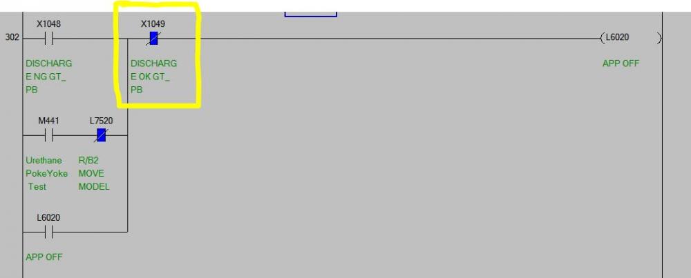
The Bits that are SET by this button are reset by the PLC on a up-pulse only. These functioned correctly at the time of the issue.
All the momentary bits shown are only on the HMI, and none controlled by the PLC at all.
These were supposed to break latched sequences such as this one shown here. This is what did not work as expected. But they have worked every other time before, and since without issue.
-
8 minutes ago, pcmccartney1 said:Darn near impossible to answer. Who's software platform? What version? Is it an application loaded or compiled and sent to a industrial touchscreen or PC base application? What is it talking to? Did you check the code in the PLC to see if it has permissive logic preventing the HMI from changing the addressing?
Its a GOT2000 and Q03UDE PLC
I'm not sure what you mean about permissive logic.. But like I said, this system has been running & working for years.
Is it possible that the PLC scan 'missed' those momentary triggers?
-
This button performs the 8 actions when pushed.
Has anyone ever had an issue where some actions were not triggered?
This system has been running for years, but Tuesday we had an issue where only the first 2 actions happened, but the remaining ones did not.

-
CCLink
in Mitsubishi
I made this excel sheet to help me remember, let me know if it helps you too.
-
Most VFD have a multiple input speed selection settings. Maybe that would be easier?
Or can you just use analog signal and a POT or HMI to set the output?
-
On 1/25/2019 at 5:27 AM, kaare_t said:I'm not sure what you mean by "such systems exist", but since you posted this in the Mitsubishi forum I'm just guessing you want to integrate it with a Mitsubishi controller?
I've worked with barcode readers and RFID readers, both serial connected and Ethernet connected. It's very straight forward and you just connect the reader (barcode/RFID) to your controller using whatever medium (serial/Ethernet/other). Then you interpret the numbers that are input from the reader. It's just a binary or an ASCII string...
What is more challenging is often what to do or how to process the input data:
When you have received the string, what should be done? Do you have an internal table in the controller (e.g. input from an HMI)? Alternatively, what I have done some places, is to have a MES module and integrate with a centralized DB. It can be a DB for personnel, products, gates etc. Just make a general query in the MES/DB and use the input string (barcode/RFID) as a parameter.As said, based on your question it's a bit hard to answer more precisely... Feel free to continue the topic if you have more information to add or if anything in my post is unclear.
We are Mits standardized here. Normally Q06UDV.
I have done several Barcode readers over ethernet, and am very familiar with that setup and use.
My question was more aimed at your second point about the challenge of using the data. I was hoping for some examples of how others have done that.
The MES system you mentioned, were you able to tie directly with the central ID system or did you have to create a separate copy of the database?
-
As part of a request to control some processes, and discussing the shortcomings of unique passwords, or keys, they asked if the company badges could be used instead.
I would imagine such systems exist, but does anyone have experience with them?
-
I have posted this example in the past. It is not using SOCSEND/RECV but using the GP.READ i was able to get reliable communication between 2 PLCs.
Only requires the one PLC to be modified, and you pick what addresses you want to read/write to on the other PLC.
-
I would probably setup the various connections in different D addresses, then use a timer/step logic to connect to each one by one. I think you'll be surprised how fast it still is pulling the data.
-
Gambit is correct. In my example that you used, I was reading from Network 3 (D2004), Station 1 (D2005)
with Your PLC Settings, you should be reading from Network 1, station 2
Also in my example, under OPEN SETTINGS, I was setup as [ TCP, Unpassive, Receive, No Procedure, Disable, No Confirm, 20512 ]
You have Send and Confirm. I dont remember exactly what those settings meant but I know I have it working..
Direct Ethernet connection is fine BTW. No switch or crossover is required.
-
I have not used personally, but I have tested the system from Ewon VPN Systems. They even have a Mits demo online to play with
-
The above will work, but just to give you more options.. I have been a fan of the NOT-NOT style rungs for large groups of OR.
|/A|---|/B|---|/C|---|/D|---|/E|---|/F|---|/G|---|/H|---/----(OUT)
-
you do have the subnet set to 255.255.0.0 in all PLCs right? You mention a test leaving it blank, but i think that would actually default it to 255.255.255.0
-
I have never used the function block method, but I would bet the Station number still matters, so verify the network numbers match and station number should be unique for each PLC.
"Only get the plant friday night" -- this sounds all too familiar hahahaha
if you have some extra PLCs laying around I highly recommend setting up a test bench, that was the only way i got the communication worked out.
-
Assuming your entire network is 192.168.*.* based, if you are on a 10.25** network that might be an issue.
I believe you would setup each PLC to be network 1, station 1,2, and 3. Then use [Station No <-> IP address] to point the stations to the other IP
then using your GP.READ you setup which station you are reading from.
-
That PDF is incredibly detailed.
-
Utilize project only allows me to select another GTW project, not the GTX project from my GOT2000
-
Downgrading because I am trying to copy the screens of an existing system to create a new one, but we parts bin shopped and I have 4 GOT1000's to use.

CONNECTING PLC with CCLINK J61BT11N through c# visual studio code
in Mitsubishi
Posted
plcModule.ActLogicalStationNumber = {StationNumer you set in MX Component};
int result = plcModule.open(); //Open the comm port