

WattUp
MrPLC Member-
Content count
141 -
Joined
-
Last visited
Posts posted by WattUp
-
-
You can either reset everything OR if possible connect to a larger resolution screen.
I have this issue all the time bc at my desk (QHD Sreen) i set the cross ref list on the opposite screen. But then line-side that list remains off screen.
-
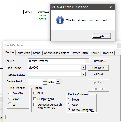
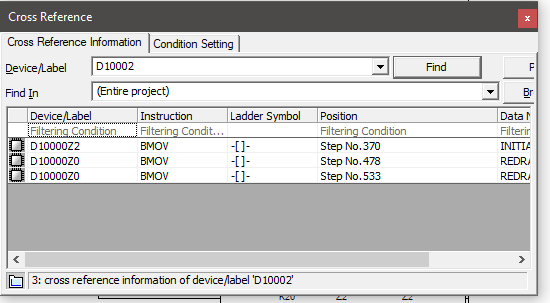
instead of using FIND for the D10020 address, which will only show contacts or coils directly addressed as such.
use cross reference. That will show any place that address is used in Bulk moves
See examples from my program.
 1 person likes this
 -
OH yeah of course good catch. I don't know why XOR was in my head..
-
This function does exist, and its EVAL
QuoteFunction
(1) Converts character string stored in the area starting from the device number designated by
 to 32-bit floating point type real number, and stores result at device designated by (2) The designated character string can be converted to 32-bit floating point type real number data either in the decimal point format or the exponent format.
You will have to clear that "G" with a XOR "FF00" D200 first
-
OH going from ASCII String to numbers... not sure that happens without some ASCII lookup table
What control do you have on that the input field / method? It would be better fix the data source than write a algo to convert
-
will this string always start with "G" ? If so, Change your HMI input to be Float input and just add the G as a prefix visually
If not, then a block move (BMOV) starting at the second register of your string address would drop the first characters.
-
Yes, you would want to add a start/end address that would be retained always. If memory space allows, i would just set this to the entire range of D. If not I typically would use 10,000 - end, that way I know the data location is up out of range with the rest of my address mapping.
I believe the HMI can have it's own memory, but I don't utilize that so i am not 100% sure.
1 person likes this -
Project navigation PARAMETER > PLC Parameter.
Then select the device tab.
Any data points listed under Latch 2 Start - End will remain through power outages / reset.
1 person likes this -
I would check the physical motor install, verify bearings are good, check runout / alignment, things like that would cause the drive to be working too hard.
Also recommend plugging into the drive and using the software to monitor the drives performance. it might point you in the right direction.
-
19 hours ago, JS21 said:Even though the program is not very complicated with only 4 inputs and 6 outputs, the logic between the Ins and Outs is entirely undocumented,
With that low number of I/O I would bet its mostly an order of operations & timer based system.
It might be a good idea to try to create a map of the functions you KNOW it does and build from there. A scope or meter on the outputs to get a timing and order. if there is a HMI look for any settings / parameters.
-
Glad to help.
-
PLC Parameters > Device Tab.
Set a start / end address for the Latch 1 / 2 as needed. Latch 1 is data retained during power cycles but reset with Latch clear command. Latch 2 retains data always.
-
-
Your screenshot shows un-compiled code (as well as an incomplete rung).
First complete the rung by tying Y0 contact to where it needs to go, probably a vertical line before /X1.
Then compile your code <Compile Menu> <Build> (F4 - Shortcut), if you are online with a Running PLC than Shift+F4 for an online build.
Then save your file.
1 person likes this -
On 8/27/2021 at 8:44 AM, Crossbow said:There should be an action to close a window page, or perhaps set the window page number displayed to zero?
This ^
Set your button with two actions, one for the pump switch and another for window screen = 0.
1 person likes this -
you could try to uninstall with Revo Uninstaller. It includes extra steps after uninstall that scan registry and left over files for a true clean slate.
-
UL508 : Standard for Safety of electrical control panels.
QuoteThe size of insulated conductors inside an industrial control panel cannot be smaller than 14 AWG. Actually, for Industrial Machineries, for low rated power motors, even size of conductors smaller than AWG 14 can be used inside the control panel (Table 66.1A).
-
I believe if the programs are linked to a navigator file, you should first open navigator, and then open the HMI from there. It might be upset if you open the HMI file directly because navigator has the files linked.
2 people like this -
-
-
Little more detail in case you are new to the Mits PLCs
M are basic internal relay bits.
D are basic internal Words
L are Latched internal relays (their state remains through power cycles)
X/Y Obviously inputs & outputs
T are timers
C are counters
Z are pointer modifiers i.e. [MOV K150 D100Z1] would move value of 150 to D100+(Value of Z1), so if Z1 = 10, D110 would
1 person likes this -
Could you instead make 1 button, but change the function in the PLC depending on the condition? You can even make the Text change based on the condition too.
1 person likes this -
I had a similar symptom 2 years ago.
We had a terminating resistor installed across DA-DG instead of the correct DA-DB.
Just one more option to check.
-
---| Running Reverse | --- [ = Count K1 ] ---------------- [ MOV K3785 Count ]

Mitsubishi GTDesigner 3 Alarm Summary
in Mitsubishi
Posted
I believe alarm ID allows you to set up separate alarm histories, but all of my systems that is just left at 1 (and also set to 1 in the User alarm observation)
Under the Alarm Display > Setting Tab > Make sure Display Target : ALL ALARM, this should show all current alarms