

Jobbe9000
MrPLC Member-
Content count
22 -
Joined
-
Last visited
Posts posted by Jobbe9000
-
-
Been searching for some info on this.
I have not been able to find something that i think i really trustworthy yet...
Only this sheet documenting execution times and memory usage for instructions up until Studio5000 V21.
https://rockwellautomation.custhelp.com/app/answers/detail/a_id/55244
I am not sure that this is the truth, but to me it looks like the instructions take up the same amount of memory. (still there is a difference in excecution time... and looks like ST is slower than ladder)

There are no memory usage in the structured text tab, for the instructions except the IF..THEN..ELSE statements in the bottom. (This is why i think the instructions take up the same amount of memory)
From what i read, the place where you will gain most memory, is by optimizing your tags... Etc. dont declare boolians, but instead declare either a DINT or an array of boolians.
Rockwell 5K processors work in 32bit, so all tags you declare will minimum use 4 bytes.... 32 single bool's will use 32 * 4 bytes, where a single dint with 32 accesable bits will only use the 4 bytes.
Now theese numbers above is only "theoretical", because apparently when using the newer versions of Studio5000, memory is also reserved for the tagname and tag description.. I did not know this untill i read it the other day, and i was really surprised with the tradeoff in memory you have to make, to be able to upload a full program with tagnames and comments.
Would be cool if anyone actually know the details, because it is kind of hard to find info on this.
1 person likes this -
You could trigger a MASR and a MAFR instruction before you trigger the MSO instruction.
Make sure that the axis.ShutdownStatus is false and that the axis.AxisFault = 0 before you trigger either of the MSO instructions.
You should be able to see what caused the axis to fault in the axis log if you want to figure our why the axis faults.
-
4 hours ago, djoey said:You would use the MSO to enable the drive again, right ?
Yes, excatly.
4 hours ago, djoey said:Do i absolutly need to home(MAH) the servo after a MSF?
No, you do not need to home it after the MSO.
You can use another MRP instruction if you need the position to be a certain value once you enable the axis again.
-
Okay, i understand.
3 hours ago, djoey said:Is there a way to stop the positioning after the Position was reached? Maybe with a MAS instruction?
The motor will try to keep it position as long as it is enabled, no matter what.
There are ways to overcome a problem like this.
The simplest way is to simply disable the drive after the MAM is done using the MSF instruction, and then enable the drive again after the welding is done.
Instead of readjusting, the motor will then just coast.
-
2 hours ago, djoey said:By "Readjustment" i mean the servo moves till the defined Position and then tries further to reach that Position again(just like it never achieved the move). The servo pulls a film down and that film is seal by two jaws. The Problem sometimes is that when the cross jaws hold the film to seal and cut it, this film moves up a little bit.
Sounds alittle bit like your servo could be overshooting. What are the maximum deceleration set to in the planner ?
You have variables on the acceleration and deceleration. When are these changed ?
Only thing is that if it is overshooting, then it is strange that it only happens sometimes....
2 hours ago, djoey said:Is it maybe a way to trend that or how can i check it?
Yes, you can set up a trend with the .EN and .DN bits from the MRP instruction, and the .IP bit from the MAM instruction.
If the .IP bit from the MAM instruction is set before both the .EN and .DN bits from the MRP, then the MRP instruction didnt finish before the MAM was started.
-
Hi djoey,
By "Readjustment" do you mean that the servo moves twice, or that it moves in a "not expected" way ?
The only guess i have so far, is that the MRP instruction is not completed before you execute the MAM instruction.
As Rockwell states in the manual
"The instruction execution MAY take multiple scans to execute because it requires multiple coarse updates to complete the request. The Done (.DN) bit is not set immediately, but only after the request is completed."
That might explain why it only happens sometimes.
To fix this, you could try to add 2 XIC after the MRP instruction with the MRP motion instruction .EN and .DN bits before the MAM instruction is triggered.
I hope it will help you.
Good luck.
1 person likes this -
Hi,
Take a look at point 2.4 in this PDF
Basicly ladder (LAD) and fuction blocks (FDB) will have an intermidiate compiling step during runtime into STL before compiled into machine code.
Siemens SCL (ST) will be compiled directly into machine code, just like STL.
This is changed with their newer PLC's 1200 & 1500.
1 person likes this -
Hi Derreck,
The .PC and .DN bits are cleared in the "pre-scan" the next time you execute the motion instruction.
This is intended as written in the help file for the MAM instruction. "The PC bit stays set until the rung makes a false-to-true transition."
Like you mention yourself, using only the .PC bit might cause problems for a state machine if not properly handled.
What you can do is use the .EN bit together with the .PC bit.
From the help instruction "The EN bit stays set until the process is complete and the rung goes false."
The .EN bit will be reset when the rung with the MAM instruction is set to false, and when the MAM instruction is called once again, doing the before mentioned "false-to-true transition", the .PC bit will be reset before the .EN bit is set.
Some people also use the inverse of the .IP bit together with the .PC bit.
This also works, 99% times.
-
Hi Maha,
Take a look at this link
https://www.youtube.com/watch?v=zz78qkWjRIc
In the video he is adding a EDS file to the DTM Library....
I bet you can proceed in the same way with your GSD file, as long as you select the profibus system instead of ther ethernet/ip system.
-
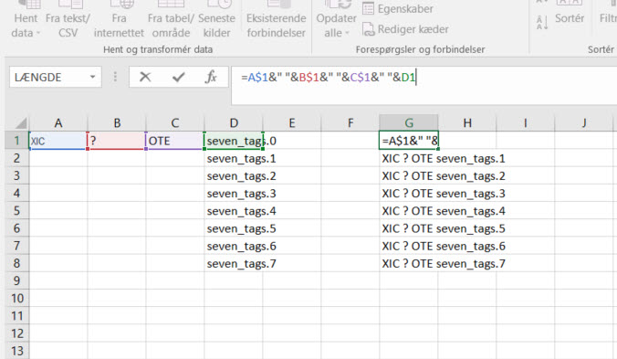
I just used the text to columns in excel 2016, with just a "Space" as delimiter. and excel break is into 4 cells.
Cell A1: XIC
Cell B1: ?
Cell C1: OTE
Cell D1: seven_tags.0
Then dragged the lower right corner of cell D1 down to "seven_tags.7"
Then in Cell G1 i entered =A$1&" "&B$1&" "&C$1&" "&D1
and dragged cell G1 down to G8.
This will solve your question about excel, but i dont think you are able to import it into logix again.
If you want to able to import your changes to logix, firstly try to export your routine with just " XIC ? OTE seven_tags.0" created in it, and open the export file in a text editor.. You will see that logix uses XML, Nice!
This is the part you want to copy and modify:
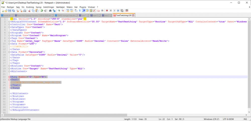
Copy this 7 times and increment the rung number and seven_tags.index.. Save your file and import the routine back into logix.
You can use excel to create the syntaxes for you, in a simelar way as i did in the above explanation.
XML should not care about whitespaces and new lines, so you can create the XML as "<Rung Number="0" Type="N"><Text><![CDATA[XIC(?)OTE(seven_tags.0);]]></Text></Rung>" and still be able to import it.
I hope it makes sense, and wish you the best of luck with your auto-generate project :)
1 person likes this -
Hi Madhura,
There are a ton of different ways to implement state machines, and alot of compagnies use their own version.
If you want to look at some lirerature, you could look at PackML. There is a lot of implementation guides and descriptions on the internet.
BUT just be warned.... implementing PackML can be a huge task, and if you only need it for this one project i would suggest that you take look at the standard and take what you find usefull from it.
PackML is maintained by OMAC, and the site AutomationML has made a pretty good implementation guide. -
Only thing that i can think of, (except if the cable is damaged) is the speed of the cylinders or one of them binding on something.
Sometimes there are counter and adjustable throttle valves on theese.
I know you have 1 second as discrepancy time which should allow for most binding in either one of the cylinders.
Uneven cylinder movements might be the cause of this only happing "once in a while"
But again... Same thing could a damaged cable :)
I am not sure that a diagnostic code is available, when you are using the dual channel conf on the input card... like it would when using the DCS block.
Finding periodic faults can be a hassle, but i am hoping you will figure it our!
Happy troubleshooting :)
-
Hi Glenn,
I havent tried this, so can't say that it will work for sure... But try to take a look at page 146, the assembly instance 100 is able to return some I/O words to you...
Maybe you are able to setup in the drive, which words to return.. In that case it might be possible to get the analouge value that way.
Might be worth a shot
-
1 minute ago, Tay ChengYong said:Hi Jobbe9000,
Yes, I have RSLinx Classic Gateway installed on the Windows Server PC.
Okay, and you have recreated the topic PLC-C on the Windows Server ?
-
Hi CY,
Just a quick question, do you have RSLinx installed on the Windows Server PC :) ?
-
Hi Ng Haireen
If you look in the fault log, you will see that about 30ms earlier than the velocity error, you actually had a "Soft Travel Limit - Positive" fault.
This fault will throw an "Planner stop" exception, which tries to stop your motor with the maximum deceleration specified in the "Planner" category.If this deceleration is too steep or hard for the drive, then the "excessive velocity error" will occour.
I think you should look at your setup to see if you are going very close too your soft limits... Especially when you say that you utilize 100% of the motors speed.
The motor will have no "extra power" to compensate if it gets alittle behind, and it might end up overshooting.So to summerize, you should check what values you have in the planner category, and check if it is possible not to move so close to the soft limits.
1 person likes this -
Hi,
There should be 3 rotarty switches in the top of the module to determine the IP address. if they are set between 001..254 the module will use 192.168.1.xxx (rotary switch address).
If you wish to use an address outside the 192.168.1.xxx range, then the switches needs to be set outside that area (and also not 888).
Use the BootP or RSLinx to configure and disable the BOOTP/DHCP mode, otherwise the module will not save the assigned address.
-
Hi Dan,
It is hard to tell without having seen the program, but the motion instructions for coordinated motion, usually takes the "cordinate system" as a parameter.
If you make a backup of the project and delete the coordinate system, you should be able to compile the whole project and you will get an error from the compiler everwhere the coordinate system is used.
-
Not beeing an expert on the 6000 series, but you should be able to just connect the common (pin15) on the Kinetix 6000 with the 24VDC power supply common for your CLX inputs. Then pull a wire from where the sensor is currently connected to the CLX input and to the IO registration Pin on the Kinetix 6000.
If its just for testing purposes then that should do it...
-
The "MechanicalBrakeEngageDelay" parameter determins the amount of time that the servo drive should keep torque on the motor while the mechanical brake engages. It does not determin how much time the mechanical brake actually uses to engage.
You should raise the time, ive heard somewhere that most mechanical brakes in AB servoes uses about 200-250ms to engage.
Try to raise the engage delay time.
-
Hi,
First of all you have to remember that working with cam profiles is always done incremental, and that is why it always seem to start from zero.
I suspect that you use the MAS or MSO to "Pause" the axis?
And that you use the STO (Safe torque off) either with CIPSafety or hardwired?
When the STO is activated the drive issues a MSO by itsself, which is simalar to issuing an MAS instruction to stop all movements, gearings, cams etc. and this brakes the link between the time master and your axis.
There are 2 ways to solve this problem:
If you want to continue using a time cam, you will have to do some math and scale your time cam before starting it after an E-stop. This can however be very tricky if the axis is working together with other axes.
The (in my oppinion) better and more safe way to do this, is by looking into virtual axis and position cam. A virtual axis is not affected directly by STO because it as the name suggests, does only exist in virtually and cant cause any danger in the real World.
The way that you would handle this, is to create a virtual master, and a virtual axis excatly matching your physical axis in settings, scaling etc.
Then use a MAG instruction to gear the physical axis to the virtual axis. before excecuting the cam profile. In case of an E-stop, you will stop the virtual master and the other virtual axis and the physical axis will stop together with the master axis.
Once the axes are stopped by a controlled stop, you can activate the STO function on the physical axis, which will only brake the gearing to the virtual axis.. the virtual axis is still linked in a cam profile with the virtual master axis.
Once the E-stop has been reestablished, you are able to gear the physical axis back to the virtual axis and start the virtual master again.
I hope it makes sense and that you will figure it out.

Kinetix 5700 - Adjust geared axis speed
in Allen Bradley / Rockwell Automation
Posted · Edited by Jobbe9000
Forgot text
Hi Martin,
You are able to use both the MAM, MAJ, MATC, and MAPC instructions to superimpose an axis which is already geared to another axis.
If your application does not require to be able to run at different speeds, the MAM instruction set to a relative movement would probably be the simplest solution.
If the application require to be able to run at different speeds, the MAPC would be the ideal solution.
The virtual axis would be your master axis, and the conveyor would be your slave axis.
You could create a indexing profile in the motion analyzer which move the slave axis 1 unit per 1 master unit. Then when executing your MAPC you can pick a suitable master distance, and set your slave scaling to the distance detected by your sensor.