

Jiggadoo
MrPLC Member-
Content count
43 -
Joined
-
Last visited
Posts posted by Jiggadoo
-
-
On 21.7.2021 at 5:15 AM, VFD Guy said:Are you using managed switches?
Yes, I have managed switch
-
I have two PF527 devices in a bus. These are in the same motion group. If I take the ethernet cable off, it will not connect the PF527 anymore back to the be controlled. I can find it on the net (ping is OK) and it is not showing any fault. In the PF527, there is reading 'connecting' and in the Studio5000 axis is showing 'Synchronizing'. Any resetting from the PLC does not affect to the situation. Also taking power off and on from the PF527 does not help. Only way is that I switch off the power from the PLC and after that it will be fine. I would like to understand, what is happening at this moment when it is synchronizing and why it is not successful? Is there any other way to get PF527 back to normal state than the PLC power off / on?
-
Thanks, we are not using DLR.
Should I assume that it will make bus unstable if there is traffic both directions, without DLR.
-
Thanks, this is clear for me now. I did not know that it is the PLC program mode.
-
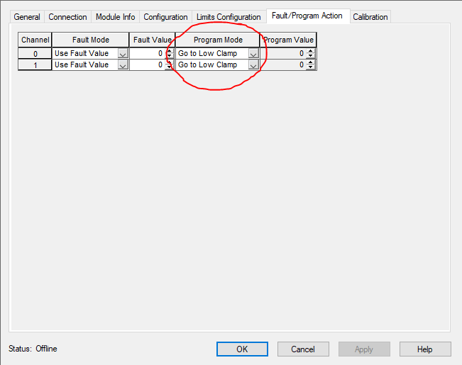
I have an analog output card 1734-OE2V and there is in the fault/actions page parameters for program mode. What is program mode and when it is activated? Fault mode is clear but... Program should be written the value, but when this happens?
-
I have an Ethernet/IP bus and system including Ethernet/IP devices with CPU 1756-L81ES ControlLogix. PLC is connected to the switch. Bus is built from the switch as a line. Can I connect the last device on the bus back to switch again? In thes case bus will be ring. Do I get problems with connection it this way. Switch is Stratix 2500, which is lightly managed switch. I believe it will increase the traffic in the bus.
-
I am building a redundant system using S7-1515R-2 CPU with TIA V16 version. Creating the hardware, there is not possible to insert any other card to the rack. Even power modules (PM) can not be inserted to the rack. How should I make the power feeding to the CPU. Should I use two power modules/devices or only one. How can I insert IO-cards to the system, is the only possibility to use Profinet IM-cards. In this system I am connecting the bus to the ring and using S2.
-
On 1.6.2021 at 4:40 PM, pcmccartney1 said:The statuses are available through the use of a GSV in your program.
I need to check possibilities to use that. Thanks!
-
20 hours ago, Jiggadoo said:I have an analog output card 1734-OE2V/C. As a default, there is selected fault mode as 'Go to Low Clamp'. I am using output range -10V to 10V.
What is the value for Low Clamp. Is it 0V or -10V? If I want it to be 0, do I need to select 'use fault value' and set the fault value to '0'.
I believe I found and answer for this, thanks for me!
Module properties page I can set the fault mode 'Go to low clamp'. And in the Limit Configuration page I can set the Low and High Clamp. So, in my case, when I am using -10V to +10V, there is set the low Clamp to -10V. This is bad in my system, when I am controlling the proportional valve. -10V is maximum to the other direction.
I need to use 'Use fault value' => '0'.
-
Is there any way to monitor ethernet/ip bus, states or faults and to make an alarm to the panel alarmlist. I am using IO-stations (1734-AENTR) and I would like to monitor somehow the system. I feel that reading the slot status of the 1734-AENTR device is not enough, because it is not possible to monitor all the cards in a slot. How to get alarm on a screen if I lose any station on the ethernet/ip bus?
-
I have an analog output card 1734-OE2V. As a default, there is selected fault mode as 'Go to Low Clamp'. I am using output range -10V to 10V.
What is the value for Low Clamp. Is it 0V or -10V? If I want it to be 0, do I need to select 'use fault value' and set the fault value to '0'.
-
Problem solved.
Stratix is using STP, Spanning three protocol. This protocol is checking the loops on the network and during this check it will block all the ports in the switch. I have been setting the smartports then enabling the PortFast Trunk. This setting in the STP page will not block the ports, although it is setting the switch to fault state for 15 to 20 seconds.
Thanks for the hint @BobLfoot and @Ken Moore
-
3 hours ago, Ken Moore said:Ports Lose Connection when Connecting or Disconnecting Device on Stratix Switch
https://rockwellautomation.custhelp.com/app/answers/detail/a_id/65469/related/1
Stratix 5400/5700/8000/8300: Changing Spanning-Tree Mode
https://rockwellautomation.custhelp.com/app/answers/detail/a_id/62769/related/1I am not able to read those links.
-
3 hours ago, BobLfoot said:@Jiggadoo something is being lost in the translation from Finnish to English I am afraid. That or I am not following your description. Do I understand correct you have three separate automation systems or cells ? Each Cell has a Stratix 5700 to connect that cells components to others in the cell and to the Plantwide network? If you power down a cell it takes the stratix 5700 some time to power up and communications to be fully functional again. During that time traffic is blocked. During this Power Up time period if you try to "link the system" {Note this I do not know what it means} the switch faults. Did I get what you describe correct?
It has been my understanding that 5700 Switches {and all Layer 3 Switches for that matter} can take up to 5 minutes to be fully alive. This is normal and anticipated behavior and should be allowed for in design.
You understand quite well, although I was writing badly.
-
Maybe I was explaining my problem badly. There are 3 systems, all are included with stratix 5700 switch. In the 1st cell, there is a CPU with Stratix 5700. In the second cell, there is IO-stations, drives, panels and Stratix 5700 switch and those are controlled by the CPU in the 1st cell. In the 3rd cell, there Stratix 5700 and CPU. Connection is made Cell1 <-> Cell2 <-> Cell3, so from the Cell2 I have connection both switches.
Now, if I power off the Cell3 and power it on again, after few minutes, all the switches will get fault for maybe 15 seconds and after that all will be normal again. If I connect for example programming device to the switch there is not any problems. Why is it so that connecting switches, it will make this connection fault. This is very bad property for our system and it should not happen. Although we have expensive managed switches, it is happening. I believe, lightly managed switches (Stratix) are not doing this.
In our system, powering up the switches with a 5 minutes waiting time is not a problem. Problem is if it will set all the switches to fault state and block the communication with the other cells.
If there is a way to avoid this, please tell me.
-
I do have a problem with Stratix 5700 managed switch. I have a system with 3 Stratix 5700 switches with their own systems. If I switch off the power one of the cabinet (including the Stratix) and put the power on again, after that switches are bloking all the trafic in the system for a few seconds. So, linking the system on will make switch to go fault. This can not be correct. What are the minimum settings that is needed to do for the switches, not to go fault during switching power on.
I have made now smartport settings for the switches 'switch for automation' => no progress. Still same.
-
I do have the panel 2711P-T12W22D9P, which can be set to PV+7 performance. I will try to set the performance on.
==> No errors anymore! Tomorrow I will see it when downloading to panel.
-
Is it really not possible to use 2 shortcuts with FTView ME panels. When I try to create the runtime file (.mer), I am getting an error that can not be used 2 shortcuts. Is there any possibilities to make FTView ME connection with 2 different PLC's.
-
Thanks for helping. You gave me good information.
Feeding power to the PF527 is coming throught the energy transmission chain, I need to check this cable and the connections. Also connection to the motor too.
Motor is used in a conveyor, there is quit fast ramp 'running speed during 1 sec'. I have not seen any problems with that before, I think this is still fine.
Undervoltage limit seems to be 65%, I think this is fine. I have not changed that, it is in a default value.
-
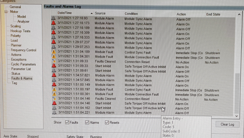
I had axis fault, which stopped the PF527. Only way to go on was to switch power off and on again.
Checking the faults&alarms, I find out that the reason was Bus Undervoltage user limit. This made 'Immediate Stop' for the PF527. Looking at the parameters, I can not find any parameter for this. In the manual it is said
'DC Bus voltage level is below user defined limit given by Bus Undervoltage User Limit, or device defined limit if the user limit attribute is not supported.'
What does it mean? Is there parameter for this limit?
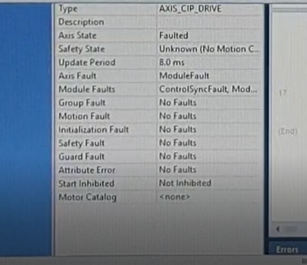
Checking the AXIS_CIP_DRIVE tag parameters, DCBusVoltage is not showing anything, why is that? => Reason found, not marked in 'Axis properties' Cyclic Parameters page
-
This is clear now, I had a wrong connection. I did not have 'sinking' connection. Thanks for helping!
-
I need to use digital outputs of PF527 drive. Controlling the outputs, it does not do anything. Relay outputs are working fine, but opto outputs do not work. For the outputs, there are relays connected, using pin 6,7 and 17.
-
Fixing the physical cables and connectors seems to help. Looks like problems were in a bad net. After the fixing net, I have not been problems anymore.
Good advices!!!
-
Hello Sirs!
I have a problem with PF527. I get alarms 'control sync alarm' and 'module sync alarm' occasionally. I suppose this meaning that PLC is missing some data from the PF527 device. How to confirm this or what should I do with the problem? Any ideas?
Motion group update period is 8ms.
Also this device is the last device in the ethernet line. I am thinking to pull the cable directly to the switch near PLC. I am not sure does it help?
How to open .ecx type files
in Allen Bradley / Rockwell Automation
Posted
How to open .ecx type files. Diagnostic data of the Control logix CPU's