

Nightfly
MrPLC Member-
Content count
99 -
Joined
-
Last visited
Posts posted by Nightfly
-
-
If this is a normal rodded cylinder then this would not work as the piston inside the cylinder does not have the same surface area on each side (because of the rod). So given the same pressure is applied to both sides, the side of the piston with the larger surface area (non rodded side) would apply a larger force than the other side making the cylinder extend outwards.
-
We use quite a few Mitsubishi drives, however we only control the speed via Modbus TCP as the run is done through a relay (the electrical designer prefers this as he likes to link it in with a safety circuit). To control the speed we simply write to the min speed parameter no 2. Been doing this for several years without a problem.
-
On 16/08/2023 at 9:31 PM, amendoza said:I'm wondering if any of you have encountered a similar situation or if you have any advice on how to handle this issue
It’s very common for programmers to map inputs and outputs to internal memory (flags) and use these throughout their program rather than raw X and Y variables. If the input or output change then you only adjust one line. Also on PLC’s where the input value can actually change during a scan (Allen Bradley) it’s basically a necessity.
-
As AndreasW said, if they are sequential then you can check they are a DWORD. Personally I always use the bits of DWORD's for alarms as it’s easier for the HMI to pull out of the PLC (as they are alarms the polling frequency is usually reasonable quick and needs to be done continually). For example pulling 4 DWORDS is usually much easier for the HMI to read from the PLC compared to 128 bits. Then you just have to check if any of the DWORD’s are not zero to generate the alarm.
-
I had not heard about this either - thanks for the share.
-
We have a function block that increments a DINT off the one second timing flag - counts to over 60 years. Do it in ST and it will copy and paste across all PLC's (one of the best features of ST in my opinion).
-
Using UDP On the Fx3U's for comms from the PC to the PLC we don’t specify the actual destination address but use 255,255,255,255 instead. Might be worth a try.
-
With issues like these i usually plug the serial device into my laptop to see unequivocally whats being sent. Use a serial port monitor (there are free ones around). I personally Just find it easier.
-
bGreen := wValue > 2500;
bRed = wValue < 2000;
bAmber := NOT bGreen AND NOT bRed;
2 people like this -
Think this means the input X values in your program do not match the PLC. Basically, in the source they are all off. In the PLC some inputs are on (X0,X1,X2,X10,X13 etc). So nothing to worry about and frankly expected.
-
Nope, thats all you have to do.
-
Not done much with the 3G, but if I remember correctly it does not have much in the way of string handling. Normally you would use an Fx3U to do this with the VAL function. You could do it the long way and convert the ASCII by your own code. If it’s coming into the PLC serially then depending on how the comms is set up you may find the data is not always at the same location in the buffer every time (so you have to search for it before you convert it). I have done this before mainly for reading load cell values coming in serially. If you went down this path I would recommend that you set up the PLC so that each ASCII character is encoded in one word (turn M8161 on), as it makes comparing the ASCII characters so much easier.
How is the number formatted in the string?
What software are you using?
-
You can often do this using the HMI as a protocol converter. We do this all the time using Mitsi drives and AB PLC's. However, this is just for simple stuff where we are just changing the speed and the update time does not really mater.
-
As glavanov said,
You need to reboot the PLC or set the Ethernet module's buffer memory address 1600 to a value of 2 to apply the setting.
-
Quotedon't have Ethernet/IP module on FX5 and i don's know if PLC built in Ethernet will do the job.
Shame as the Ethernet/IP module for the Fx5 works really well - In fact I prefer using it to CC-Link (I find it much easier to setup).
-
Does your application have a HMI? I always find it easier and quicker to print using the HMI (serial or Ethernet) than the PLC. However this depends on the vendor - some HMI’s are more flexible in this matter than others.
-
Depends how accurate you want it, but you could always periodically simply increment a DINT. Have one that counts up every second (no need to reset as it’s good for over 60 years). When something starts, copy the value of the DINT to a “start time” Register, same when it stops. The time in seconds is obviously stop time – start time.
1 person likes this -
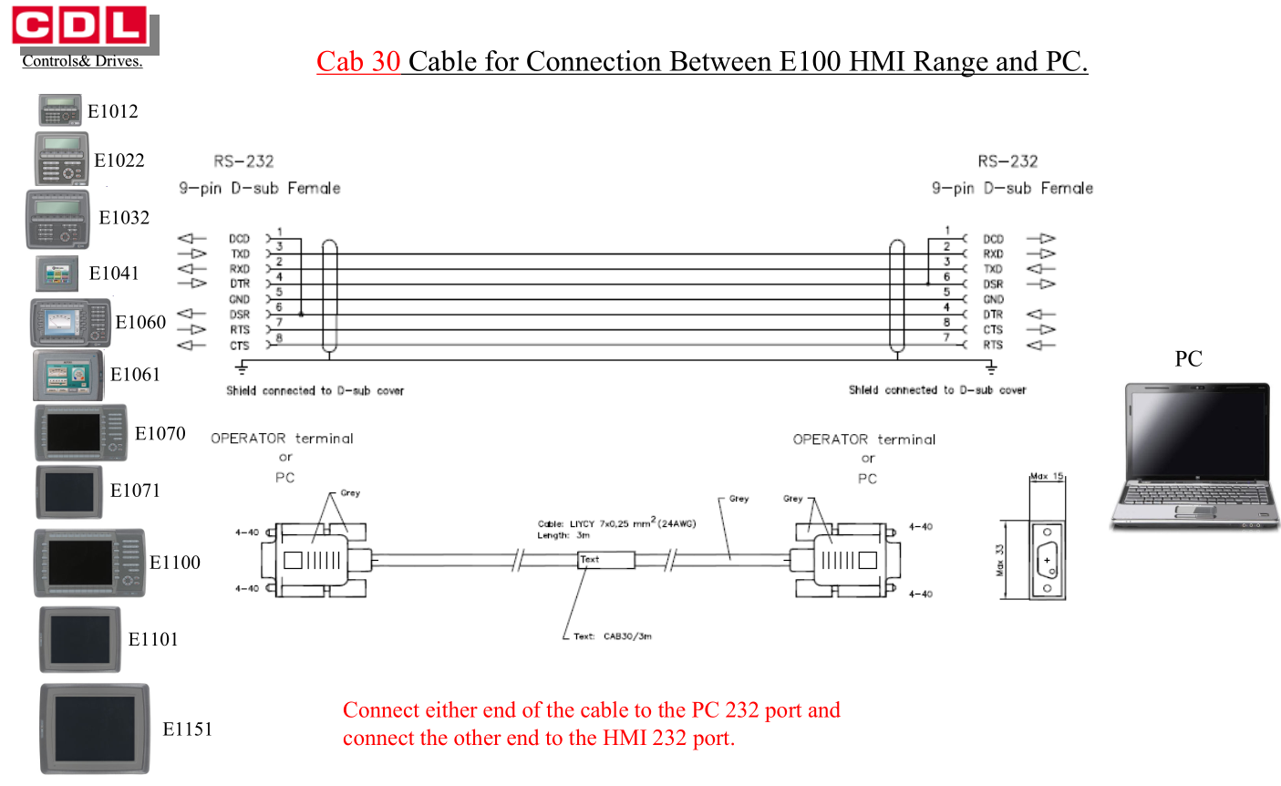
For an E610 HMI you use a Beijer CAB5 cable (simple three wire).
For an E1061 you use a Beijer CAB30 cable.

-
As far as I know it is a compiled resource file, the contents being bespoke to Beijer.
-
Hi,
If it can't match the driver then have you any Mitsubishi PLC drivers actually installed? There is an option to update them under the File menu. Select File->update Exter drivers from the internet (or something like that). Select all the Mitsubishi ones and download them.
As far as I recall (and I could be wrong), originally Exter HMI’s could not be used with Mitsubishi PLCs because of a Beijer contract to supply the same units to Mitsubishi badged as the E1000 series. So they removed the drivers. However, this changed later when the two companies fell out. You may just not have any drivers installed.
-
The HMI you are trying to program is a Beijer Exter, You need the program “Information Designer” to do this not E-Designer. E-Designer is used only for Mitsubishi HMI’s (I know the HMI’s look Identical but they do need different apps to program them).
You will also need to convert the project so Information Designer can read it. I wrote a small App to do this a few years back. It can be found in the downloads section of this site.
Warnings about file creation versions and different driver versions can usually be ignored and the HMI once converted and loaded into the HMI will work perfectly fine.
1 person likes this -
As Neverov said, all the addresses are screwed up.
For example if you want to read outputs then they are sub 1000. Output frequency is at address 201, amps is 202, thermal overload % is 210
If you wanted to change the minimum speed parameter you would write to address 1002
Also (as Neverov said), the slave address must be set to 255 otherwise it will just ignore requests. I have found that on many Modbus communication applications this is not an option for TCP. The free qmodmaster does have it though, and is what I have always used to test comms om Mitsubishi Inverters
https://sourceforge.net/projects/qmodmaster/
The settings below are what I have used before for reading data into a PC using Modbus TCP. These setting just allow monitoring and the read/Write of the parameters. They do not allow you to control it (turn it on/off) as this was done via digital inputs.
73 Analog input selection 0
77 Parameter write selection 2
79 Operation mode selection 2
160 User group read selection 0
161 Frequency setting/key lock operation selection 0
178 STF terminal function selection 60
179 STR terminal function selection 61
180 RL terminal function selection 4
181 RM terminal function selection 9999
182 RH terminal function selection 9999
195 ABC1 terminal function selection 99
196 ABC2 terminal function selection 98
502 Stop mode selection at communication error 4
550 NET mode operation command source selection 9999
551 PU mode operation command source selection 9999
779 Operation frequency during communication error 15
1424 Ethernet Communication Network Number 1
1425 Ethernet Communication Station Number 1
1426 Link speed and duplex mode selection 0
1427 Ethernet function selection 1 5001
1428 Ethernet function selection 2 45237
1429 Ethernet function selection 3 502
1431 Ethernet signal loss detection function selection 3
1434 Ethernet IP address 1 192
1435 Ethernet IP address 2 168
1436 Ethernet IP address 3 100
1437 Ethernet IP address 4 1
1438 Subnet mask 1 255
1439 Subnet mask 2 255
1440 Subnet mask 3 255
1441 Subnet mask 4 0
What is the reason you are connecting the inverter to the PC?
-
If it streamed data to the PLC continuously then I would query the use of the Bidirectional Protocol. Did you read that this was required somewhere? I would assume Bidirectional may want handshaking other than the software XON/XOFF that your 3 wire connection can give (and if it was streaming continuously to the PLC without software handshaking then the Scales are not using it). If so this could be why you are not receiving data. For streaming data perhaps the Non Procedure Protocol is the way to go. However, you will probably have to format the data yourself and often even have to find it in within the data array received.
-
Regardless of the serial device (RS232/422/485) I always feed it into a PC first to see what’s happening. I wouldn’t bother with all the jumpers, just wire 3-2, 2-3 and ground and monitor with your favourite Serial port Monitoring tool (there are a few free ones about). It takes out a lot of the guesswork as you will be able to confirm that the Scales are actually streaming the data, as well as the format it is in (but you will need a serial to usb adapter).
Pilz & FX5U communication
in Mitsubishi
Posted
Ethernet/IP is not a "Standard" Ethernet socket connection. I think to talk to this device you need a FX5-ENET/IP module. This is what we use to talk to Ethernet/IP devices such as Inverters / Loadcell's etc.