
panic mode
MrPLC Admin-
Content count
3016 -
Joined
-
Last visited
Posts posted by panic mode
-
-
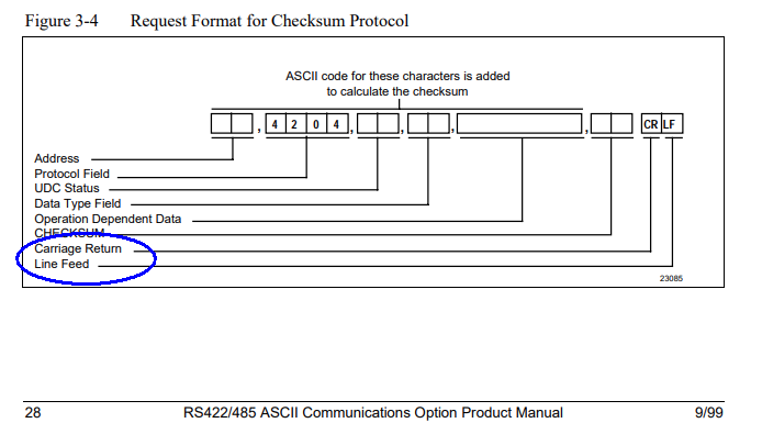
also note that comma separator is still needed when no checksum is sent (see 3.9 Loopback example)
so the message should be
02,0204,64,11,128,
followed by ENTER,
Loopback can be used to scan network for attached nodes.
2 people like this -
no response at all? i would check wiring, terminations, baud rate, correct node address...
-
this is what i would try:
02,0204,64,11,128,00
followed by ENTER
-
no idea... i would try all options. i think manual mentioned that checksum is options but it did not specify if it is to be omitted or populated with something random like "00" so you will have to try. my main point is that termination was incorrect and instruction was likely rejected because of that, even if correct CRLF is encountered after that... this really should be quick and easy to try. now that i think of it, it is probably needed (same fixed format) but value is simply not evaluated by device. so your message looks ok other than CRLF.
other than i would question if COM port settings match the target or if wiring is correct. Are you getting any response back? if so what does it look like? if you do not get anything back, chances are that wiring is incorrect. if replies are garbled, then port setting config is not right (wrong baud rate, data bits etc.). also are you sure that node address of target device is correct (2?)
-
btw manual shows that too:
 1 person likes this
 -
changing hardware for a newer may be a smart idea to avoid obsolence but it will come with a cost (hardware and programming) and will not change anything if message is in wrong format. and i think that is what you are dealing with...just checked your post closer and see this:
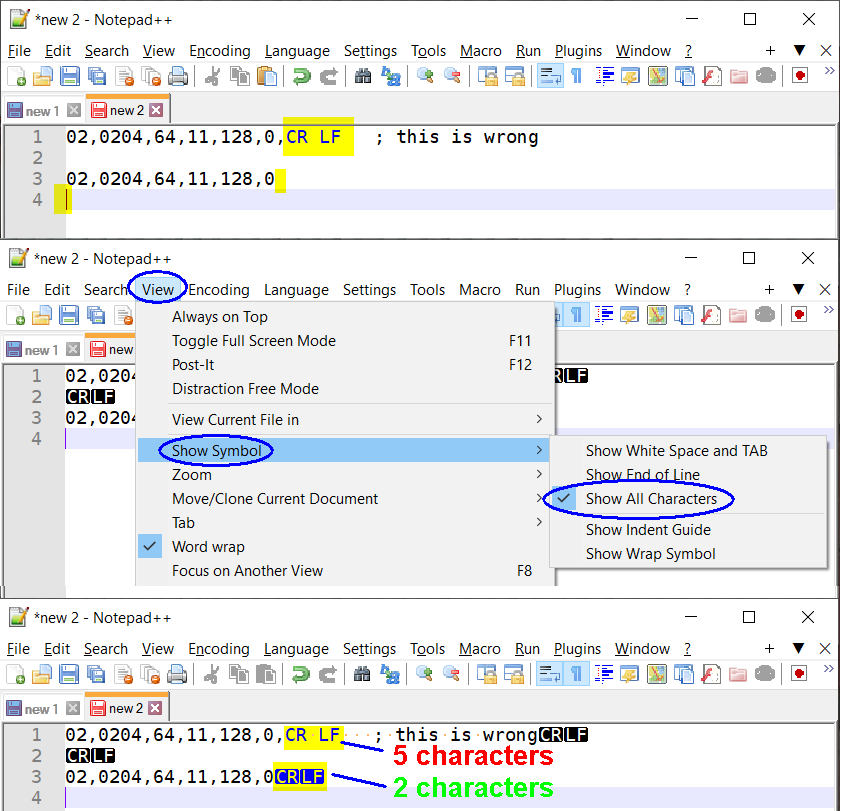
The "CR LF" is supposed to be just a pair of characters (only 2 bytes), but based on your screenshots you have entered it as string of 5 characters. also since you are sending message without checksum, the last comma is likely also not needed... (maybe)
CRLF is normally added when you type command using keyboard and hit ENTER.
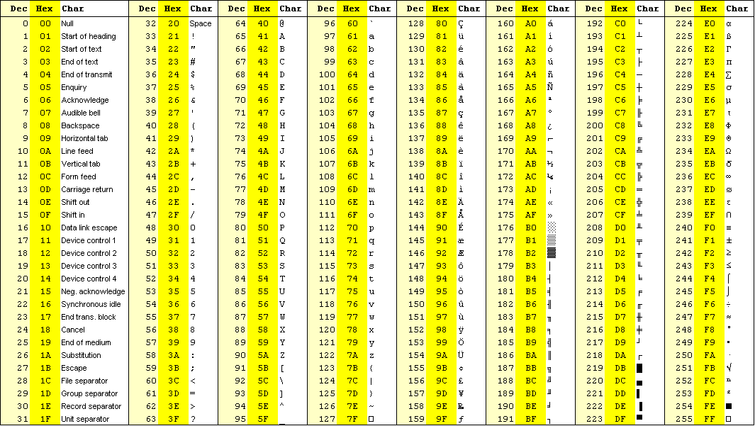
CR is Carriage Return and has value 0x0D
LF is Line Feed as has value 0x0A
in a file you would need to do the same so that next line is shown (see lines 3 and 4)
for more details change view to show all characters and you will see why.

 1 person likes this
 -
go to properties, settings, ascii setup
 1 person likes this
 -
it's been a while since i used Omron and FINS. maybe there is something newer too but did you try Google:
-
the masking operation need to use AND, not XOR...
XOR with 0xFF would change 'G' (value 0x47) to value 0xB8 which is not what you want. in fact one may probably want this value to be a non-zero since zero may be seen as end of string. so space character would likely be safe choice... (setting that would need an OR instruction)
1 person likes this -
"it is simple" does not describe it... why don't you post your code and explain your test method or how to reproduce it?
what is connected to X0 and X1?
are you sure that logic is scanned?
are you sure that M100 is not used anywhere else?
did you try some other bit instead of M100 to make sure it is unused?
-
-
That is a great idea... And so simple. To
-
i have never uses that robot but based on quick internet search it seem to be a small robot arm (scara). btw. AWC board is not just an Etherent card... it is an entire motherboard (controller) with a lot of functionality. Did you follow the instructions in the manual on replacement?
flash card is substitute for a HDD and contains OS etc.
but key system settings (robot serial number, licenses etc.) are stored in NVRAM.
when AWC is replaced, all settings need to be transferred, that includes flash card, NVRAM, address configuration...
not sure what the "protection error" message is but may as well be complaint about missing license.
-
you can have bunch of HMI buttons, each setting different bit in some memory area. at the end of PLC scan you can let PLC reset the entire area. for the rest of your PLC code, each of the bits will be seen as one shot. that will work rather nicely for plenty of cases and it is very efficient (no timers, very simple logic, no way to stay stuck etc.). if for some reason write message was missed, user would see no response and simply repeat pressing the same button.
but while simple, this does not work in all cases. an example is where you want to use button to jog axis (and releasing button is suppose to stop the jog). in that case one can resort to some alternative to make it robust. one simple way to get around this is to have HMI cyclically write entire block of memory. this way even if one message is missed and thus desired change is not seen by PLC, the very next message will overwrite the entire block and correct the situation. this is pretty much of how fieldbus data transfer works so all received signals seem to be continuous and instantaneous. this is also quick to implement when one is making custom HMI (a PC application using own driver or implementing just two functions of some SDK - read one memory block and write another...).
but this is not how most HMIs work since it is limiting (all write requests need to be in one block). but typical controller may have many different memory areas (timer, counters, inputs, outputs, memory bits, data registers, retentive memory locations etc) they would normally send commands as individual writes to each individual location. so number, size and type of write messages would always differ.
therefore one may dig into the bag of tricks and do something fancy depending on particular platform capabilities.
and as you have already stated - if something is really critical, it should be handled as such and use more reliable solution. for example robots are making use of enabling switch (a safety device) allowing user to stop any motion command even if jog button was to fail.
-
ACE3600 ?
-
maybe... did you check the instruction list?
and you should always post your code and expectations. (resolution, time span, accuracy...)
if i read this right you have a problem due summation since average is computed by:
AVG(n) = (X1+X2+...Xn)/n
it appears that you are attempting to store top side of the fraction into one variable and of course this will overflow pretty soon.
solution to not do that... note that the very next average will be
AVG(n+1) = (X1+X2+...Xn+1)/(n+1)
but this can also be written as this (isolate last term)
AVG(n+1) = (X1+X2+...Xn)/(n+1) + Xn+1/(n+1)
or
AVG(n+1) = (AVG(n)*n + Xn+1)/(n+1)
but that will overflow the same way as before due multiplication AVG(n)*n.
however this can be rewritten as
AVG(n+1) = AVG(n)*n/(n+1) + Xn+1/(n+1)
where AVG(n) is previous average, Xn+1 is the latest sample, and "n+1" is the latest sample count.
as long as you compute n/(n+1) before multiplying AVG(n), there should be no problem since n/(n+1) will grow but never exceed 1.
ultimately this will settle at some average value since limit of Xn/n goes to zero as n goes to infinity so adding more samples will just add zeroes and average will stop changing.
this begs question... are you really really sure you need total average over indeterminate and always increasing time interval and not average of several most recent samples? one would normally look at average only over fixed number of samples. that number can be small or large but it should be fixed.
if you really want to cover "endless" interval, you need to define what is "endless".
1 person likes this -
using half of the range is equivalent of loosing one bit. 0-5V is quarter of the range -10..10V so that would be reduction of 2 bits. i don't think that would make much of a difference for most applications. but if it is an issue one could add pair of resistors to form a voltage divider, that would allow use of up to 1/2 of range. still not worth the trouble in my opinion.
NX-DA2603 : each channel has 8000 count over full range. (1/4 of that is 2000 counts)
NX-DA2605 : each channel has 30000 count range (1/4 of that is 7500 counts)
-
why can't you use it? you can limit in software value range and last i checked 0-5V fits inside -10..+10V range.
1 person likes this -
you will be well served with those but nobody can tell what the future will bring. programming in general is young discipline and evolving fast.
2 people like this -
4 hours ago, BobLfoot said:tease your brain and add some good clean fun ones.
hmmm... the word clean is taking all fun out of it...
 1 person likes this
 -
2 hours ago, pszczepan said:As I wrote i did tick OFF and ON and nothing changed
that is exactly opposite of what is in linked instructions and suggestions.
when checkmark is set, function is disabled.
-
they are quite similar, both have similar instruction set, both require declaring variables to hold some value (cannot enter literals). i prefer look of thin lines of plc fiddle and more intuitive insertion of instructions but plcsim online has better handle on scrolling, instructions are in one group and always visible.
https://www.plcfiddle.com/fiddles/0fce9df0-da52-4db5-afbd-770773b77465
-
i think you meant to use word searching instead of finding.
-
unlike https://app.plcsimulator.online/ plc fiddle does not work on mobile phone but otherwise it looks very similar in capabilities.
1 person likes this
Omron IO-Link and Baumer RR30 sensor
in NJ Series / Sysmac Studio
Posted
yup... when troubleshooting data exchange issue it is a good idea to see both sent and received values in hexadecimal format. that will quickly identify any discrepancy in endianness. the other option could be that values are inverted... unfortunately documentation is not explicit of used format and no sample value is shown so this means more legwork identifying what the value format really is. can you post one or two sample values (preferably in hex) and actual sensing distance (expected value)?