
panic mode
MrPLC Admin-
Content count
3016 -
Joined
-
Last visited
Posts posted by panic mode
-
-
you can replace it with many products. the question is why... are you running out of I/O or need something that you do not find in that product? alternatives are likely going to cost more not to mention time to create documentation, code and have it all approved.
-
using speed control allow you to control the speed but it will not get you precision when it comes to position. for precise position cuts you need position feedback. doe your axis have an encoder?
-
well, time is running out, got to make it work...
drive memory is organized in menu/parameter fashion. until i have time to investigate closer, i will be using few unassigned menu locations. this is less than ideal since they are scattered ... would prefer single (or two) blocks of memory without tiptoeing around used ones.
oh well...
-
hello everyone,
I am able to connect to servo using driver device/server "Control Techniques SI-Ethernet Modbus TCP". this accesses servo by specifying memory locations in form of menu entry and parameter number. But i need to exchange more than that. drive has built in PLC and i did not find out what device driver or settings would allow that.
any ideas?
-
did you try manually setting the outputs on? are you sure there is nothing clearing them?
did wiring change at all? problem started after program download?
-
-
those are just shared properties.
clicking on radio button 'All properties' should show longer list...
-
check the wiring including terminations. also, check the baud rate. what is the expected role of this unit? it can be bus master/slave or both. bus must have a master("scanner") and one or more slaves ("devices"). some slaves can autodetect baud rate. this is convenient when it works but unfortunately sometimes they also get it wrong and that is a bad situation to be in as there is next to nothing one can do to solve it. unlike other bus types, DeviceNet uses additional pair of conductors that need to be powered by 24VDC. somehow this is also a pretty common issue as many fail to realize that they are responsible to bring this power to the bus. some fail to ground the bus shield or they ground it in more than one place (this allows for ground loops and interference) or they strip way too much of the shield so that shielding is ineffective.
if your CJ1W-DRM21 is working as a master (scanner), you need to load correct configuration into it ("scan list" is usually created in PC software after importing suitable EDS files for each of the slaves)
1 person likes this -
using safety PLC does not mean that end result is safe. it only means that it is capable of applications requiring safety - if used correctly. ultimately it is still up to programmer to configure and program it correctly. without software one cannot check your program. you may considering printing or exporting it into a PDF form so anyone can offer feedback.
even for EStops, it is not enough to put them in series with something. safety standards have various criteria that need to be met and this is determined through evaluation process (aka Risk Assesment).
2 people like this -
coil instruction is used to assign both true and false values:
variable := expression;
or in your case
start := (i_SW1 or start) AND NOT I_Off;
I_Off := start AND i_sensor4;
...etc.
1 person likes this -
in DotNet one could use PathGeometry and ArcSegment. to go beyond 180deg property IsLArgeArc would need to be set to true
btw, have not seen it in years but it looks like required level of customization for something like this may be possible with factorytalk view studio SE as well. what properties are exposed for objects like arc or wedge?
-
VisualStudio....
initially it would be the 3rd party driver/ActiveX/SDK as this is the fastest way to get results. but that is something we rarely do today. just about all are done internally, either from scratch or by using open source or SDK if and when vendor offer it. many devices use simple protocols that are easy to reverse engineer.
the usual application would be some GUI software that has many simultaneous connections to different devices (PLCs, robots, other PCs, CNCs, RFIDs etc.). and if don't want to waste the time on something new (fieldbus etc), we just add the option (driver or hardware) to one of the system components (PLC or robot) as we can already talk to those.
-
well that is one of the reasons we went away from integrated solutions built around industrial HMIs and use industrial PCs with our own software. they are usually comfortable and learning curve is short but one has to live with limitations. for us it meant initially we had to develop more but - it is up to us what we do with it and that means everything is possible. no more limitations like screen size or resolution, number of displays, number of tags, type of controls available etc. when something is needed but not already there, we create it. once done it can be used many times and in any project.
-
i am guessing you are trying to make a custom HMI object but i cannot figure out why would border need to change and why would that need to depend on assigned tag instead of tag value.
one should be able to accomplish by scaling (height/width).
what software you are using?
-
number of pulses tells how far to move... rate at which pulses are sent controls the speed.
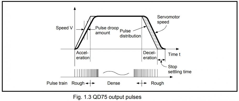
so maximum frequency of the PTO is one of limiting factors. small PLCs often have PTO that only get to few kHz, some may go to 100kHzor 200kH, dedicated modules for larger PLCs are definitely more capable (MHz). by parametrizing drive one can accomplish certain scaling so that for example axis can reach higher speed even when driven by slow PTO. but don't be fooled - this is a tradeoff... you may gain at one end (speed) but you loose at another (resolution). so one need to read the manual, do the math and set parameters correctly to get needed performance. but once you reach point where PTO cannot handle it, it is time to upgrade to more capable PLC.
2 people like this -
looks like that output is fried...
2 people like this -
get the programming manual and check it out
https://www3.panasonic.biz/ac/e/dl/manual/index.jsp?series_cd=1700
looks like FP0R has bunch of timers and can be used with different increments - 0.01s or 0.1s or 1s.
using 1s base (TMY) you can have timer run for just over 9h.
-
please do not use wrong name - you are only confusing yourself and perhaps those who try to help you.
that is clearly not a hyperterminal - screenshot shows that this is the KRterm from Kawasaki.
while features/settings will overlap (at least the core), they are not identical (may look differently, be called differently, etc). this is hyperterminal and how the settings appear::
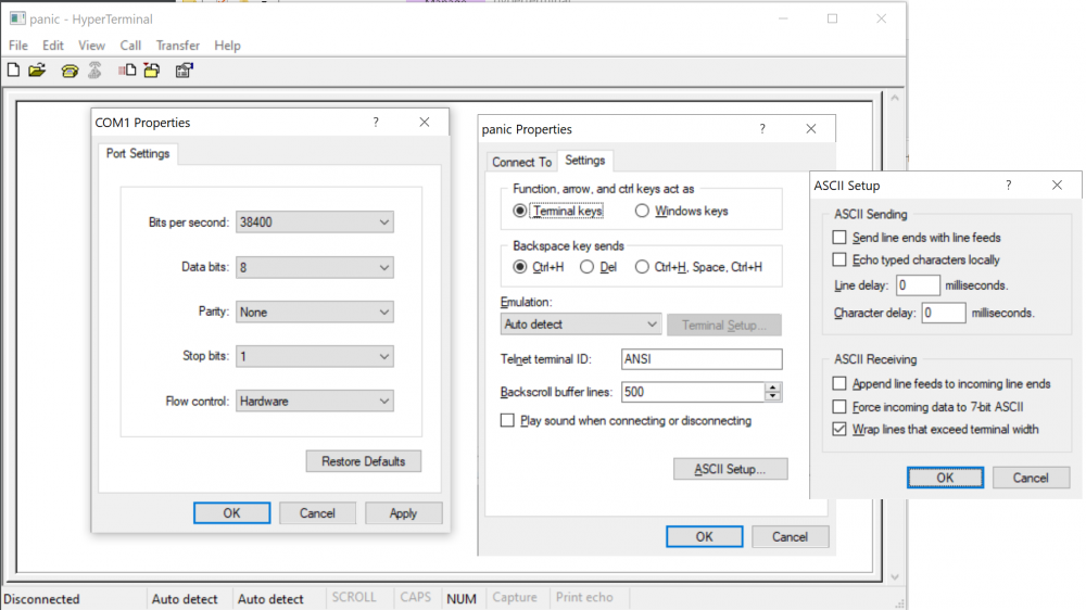
any terminal software allows you to configure some things including termination characters. so this may already be there...
there seem to be configuration software for the product. did you use it? it should allow you to confirm or set specific com port settings and everything else that product may need.
without correct cable and com port settings, there will be nothing going on. so what port settings, what cable are used. and are you even sure that you are connecting to a correct port? at least some of the devices seem to have more than one port.
AD has bunch of examples including documentation that dives into every command. your posts suggest that you only look at ViewMarq itself for response. what about getting response though communication channel that you are trying to use? for example why not ask it to report version? that should allow confirming cable, port and port settings are correct even before you send some longer command in correct format (one that may specify correct window, position, blink etc.)
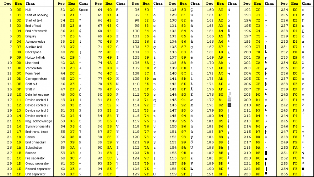
personally i like RealTerm because one can see the messages in different formats - including hexadecimal. as someone who wrote code talking to various devices, hexadecimal view is essential debugging and understanding what goes on.
this is also the reason to always have ASCII table at your fingertips:. in this case you only need carriage return which is already explained has code 0x0d or 13. Btw, that is inserted as you are done with typing of the command, or more specifically when you press Enter. For example if you are using Notepad++ to write anything, try turning on "Show all character" and you will see everything - including tabs Cariage Return, Line Feed etc.
 1 person likes this
 -
as shown, both source and destination are already array elements. so by controlling index on both ends, one can transfer data any way you like. index is the value inside square brackets. this value can be hardcoded like in your example or it could be a pair of variables that you control
-
i think last time those were made was in the 70s. they may be falling apart on their own, without user touching them.
why not use something more recent like HMI? you get way more bang for the buck...
or use panel mount LED/LCD counter module as a display, together with encoder or pair of buttons (increment/decrement) as input.
1 person likes this -
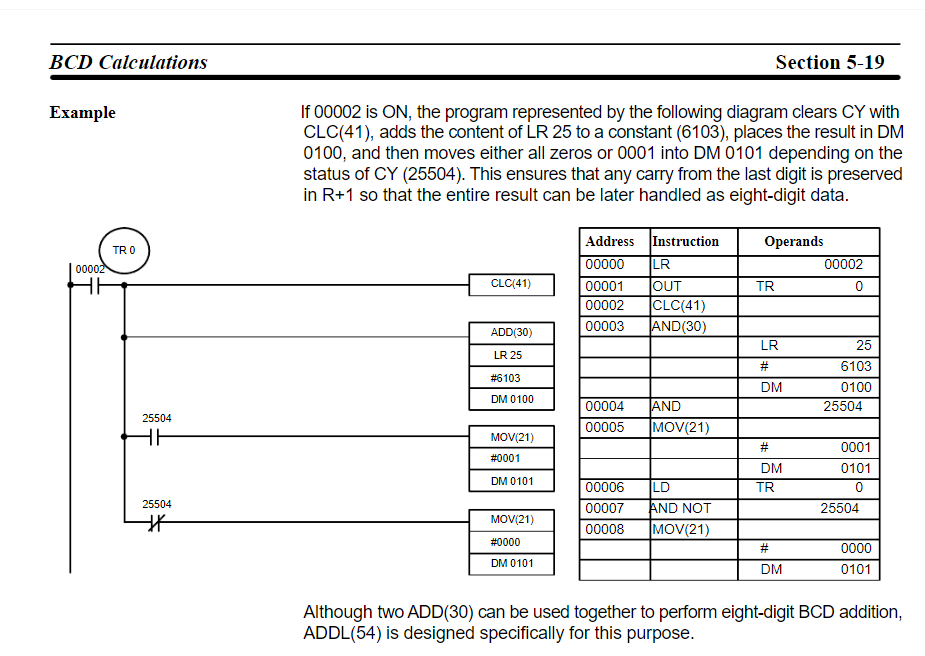
it is the same thing you do when adding numbers by hand using nothing but a pen and paper.
for example adding 597 and 895
     597
     895
(+) ------
    ????
so you start from the right side (least significant digit) and add those values 7+5 = 12. so you write down 2 (result is ___2)and remember to carry 1 (representing 10 actually) to the next position.
then you are adding 9+9 but also must include value that was carried over (1) so sum here is really 9+9+1 = 19, and you write down 9 (result is __92), and carry 1 again.
then you have 8+5 and since we still carry value from previous digit addition, it becomes 8+5+1=14. so you write down 4 (result now is _492) and you continue to to next position.
since there is no more digits in the operands, we just have the carry (1). we write this down and result is 1492.
if this was clear, you should have no problem adding numbers that have many more digits.
same is with the computers - they can only handle limited chunks of data (based on instruction type and size of registers). so to break free from this limitation and be able to handle even very large values, carry value need to be considered. and programming manual has the nice example as well.
before calculation one would reset the carry flag. setting flag is possible too but this is used less frequently
 3 people like this
 -
can you please just get to the point and tell us something about function you need:
1. what is the exact PLC model
2. what is the PLC software type and version
3. what is output really supposed to do
if you want to make single 1sec pulse when button is pressed, and really make it 1sec pulse regardless how long the button was held
down, something like this should do
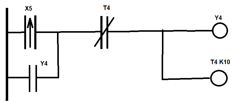
explanation
X5 is input for push button (trigger). instruction is not a standard NO contact but senses rising edge (hence the arrow up). this ensures that regardless how long button is press down, only single pulse will be generated.
rest is a simple seal-in logic:
output Y4 is held on until timer T4 times out. K10 is duration (10x base time). on most timer base is usually 0.1 seconds. so 10x 0.1sec = 1 sec.
-
What is the CPU type? That will determine instruction set. Then you can check what options are available - there could be suitable instructions for this...
But you can always manipulate data yourself. For example to extract lower byte, just AND the value with 255.
To get the upper byte use swap instruction then again and the value with 255.
-
when it comes to Ethernet/IP, AOP is used to allow single network interface to be used both for standard and CipSafety data. one can of course choose to not use AOP for this then one needs additional network card. it is same as working on PLCs with older firmware.


Two Keyence Ethercat devices not working at same time
in NJ Series / Sysmac Studio
Posted
i am not using those exact product but... i have worked with EtherCat many times and connected multiples of same nodes without issue. each physical node gets its own instance in the controller. you do not access one node to get the values to/from the other, so it does not matter that PDOs are named the same way - they are in a different instance/node.
in terms of troubleshooting first thing is always to see how they are all connected, and is the network topology correct.
lets put it this way: if the hardware side is not setup correctly, there is no hope of stumbling on correct settings in the software.
in EtherCat network, nodes are daisy chained. branches are possible but there are limitations and this requires hardware that supports this.
so once the hardware side is verified, one can deal with the software.
how did you configure it in your controller? did you scan the network or manually populate it? are you sure that topology in software matches what you have done in hardware?