

Gambit
MrPLC Member-
Content count
2623 -
Joined
-
Last visited
Posts posted by Gambit
-
-
15 hours ago, Yahya said:I can't find the document in the e-manual

That's not how you search. Download the latest manuals if needed. Then patse SH081257ENG-8C2 in the search bar but change the [ALL] button into
See attached doc
-
Not that i am aware of. Also GX Developer is not supported anymore
-
15 minutes ago, Yahya said:That's right, I want to know the communication status of the master PLC with PLC 1,2,3. is that possible?
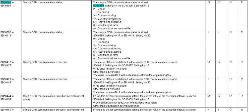
Have a look op PAGE ID : SH081257ENG-8C2 of the e-manual viewer. Checking the simple CPU communication status.
1 person likes this -
Upgrade from GX Developer to GX Works and under option in GX Works 2. Set Display STL instruction in contact format

-
If you are going to Cange you might aswell change to GX Works 2 which still support the FX series up to FX3.
As for STL is was a languge to do SFC. GX Developer and GX Works 2 both support SFC.
Have you looked at this ?
-
Check the How to use 2-phase 2-counting input counters C251 to C255 for 4-edge counting in the FXCPU Structured Programming Manual.
It has to be continious on for the X00- X07 inputs to be used for counting, When it is not on the couter is off
-
Look like you have all the communication running right ? So you question is where you can find the status of simple PLC comms ?
1 person likes this -
-
On 19-4-2024 at 7:17 PM, Saxony Thermal said:Also to your note about 16 or 32 bit results, if it were 32 output it should strongly affect my other arithmetics who rely on that device that may get unintentionally modified. But all my arithmetic results are accurate, just having this sweeping zero...
But respecting your thoughts I did the following and I find this to be an acceptable solution. Originally I was using D100 as my buffer to do calculations before sending the final result to d121, for example, via the arithmetic output. If the arithmetic still outputs 32 bit then it captures D122 which is my next analog input result that I don't want to have messed with.
So lets back up the buffer entry to D99 so it has D100 to claim making a 32bit buffer (because D101 is one of my raw analog input devices). I then have all arithmetics for all my analog input readings dump into that 32bit buffer, and then add a new MOV step to move just the D99 16bit info to D121.Attached is my new working code.
This eliminate my sweeping zero issue. None of my calculations break past 16bits but it is apparent that the arithmetic is 32bit output despite the documentation saying 16bit and was 'capturing' or 'freezing' or 're-initializing' the 32bits to 0 before doing arithmetics, and my sweeping zero was the second byte of that 32 bits that I would see in my HMI. So had my calculations overflowed 16bits, it would probably had shown non-zero instead of a sweeping zero.
I supposed my outputs were also always accurate because there was always 0 in the second byte of the arithmetic. If it were non-zero then my other arithmetics would feed in that value and go all bonkers. But zero kept them level headed.I still, totally, ignored labels in this solution. If you have good documentation or youtube videos on applying labels that would be much appreciated. Otherwise I will keep doing what I know best which is all devices. I spent a good hour trying to figure out the labels but it was fighting me really bad.
Otherwise, thanks very much!! You helped a lot.
Ther is no code attached, However I'll make a quick example of the ladder code from the previous mail in label style.
-
On 19-4-2024 at 4:59 PM, Saxony Thermal said:I did find an Array Element option when configuring the label type, but that did not resolve the error adding a second element to the array.

Good morning. You did find it but the element dimensionis only 1. It should be 2.
Also there is a easy way to cretae the correct label type. When using the instrcution just type an unknown vaiable name.
Then it will prompt for a label declaration and the right type is alreayd pre selected.
-
OUT_C_32 is needed to activate the high speed counter
Dmov is for the values
-
There is a difference between C250 and C251. 1-phase 2-count input & 2-phase 2-count input
To activate the counter use OUT_C_32 instruction
As for the monitoring keep in mind that the program is running much faster then you are monitoring.
So many scan have been processed which changed some values.Active open or closed is only what you programmed the depending on the value of the bit it will be filled blue. So a normally closed which bit is off will be blue filled
p.s. For real production i would not use a clone !!!!!
-
You should use labels than you would have gotten an error,
Some instructions Like multiplcation the result is 32 bit so it uses 2 Registers. So if you enter D120 (it's also D121)
When you use labels you have to define the type so you would have gotten a notification when building the project
-
During installation you didn't set start automatically when booting the PC. So it looks like the OPC server has't started.
Have you started the server ?
Basicallly your screencapture is already providing the correct steps
-
Which Firmware are you running ?
As for Dianostics:
-
https://www.mitsubishielectric.com/fa/document/technews/got/got-a-0160/gota0160ac.pdf
You need a USB -A on the GOT. The mini USB is only for data transfer
-
Then I expect there is something in the code on start-up. chianging the values
-
On 5-4-2024 at 5:24 PM, Bhavin017 said:Sorry but I am new in this field so i will ask some stupid question and I ask your pardon in advance.
There is one more thing, what about the HMI Switch M635? because as per logic if that switch is off then R7444 value can not copy to D2842. and everytime Eng has to go to Press after power cycle to turn that switch ON. is there any way I can maintain status of that switch?
Just Change M to an L device. Those are latched
-
Then D2842 should be lachted, So it's either overwritten in the program (maybe an inital program) somewhere after a reboot or the battery has died.
Is there a yellow LED lit on the CPU? Can you check the parameters if the battery detection is disabled
1 person likes this -
You'll need to Latch D2842 in the PLC parameters. which controller are you using ?
-
Okay In GX works 3 goto the CPU parameters. Service processing settings and give more time for communication
-
Maybe you should start in steps and get network running with the stations. after that refresh the correct Registers/adresses.
And than the need programmingThere is an e-learnig for CC-Link. you should follow this first
-
Did you use different stationnumbers for the connections ?
Do you communicate large amounts of data ?
What is the scan time of the PLC's ?
-
Why ??? you can do this easlly with the simple PLC comm settings. Ypu don't need any programming
OR if the FX5 is just the server just create a modbus port in the port settings and you're done

Mitsubishi GX Works 2
in Mitsubishi
Posted
You can download the latest version via your MyMitsubishi Account.
V1.662 is the latest one i think