

Michael Walsh
MrPLC Admin-
Content count
1801 -
Joined
-
Last visited
Posts posted by Michael Walsh
-
-
You could also use @D. It is simpler.
First scan, MOV &1 D0 - initialize pointer to point at D1
When you want to store a temperature:
MOV Temperature @D0 - Move the temperature to the address that D0 is pointing toINC D0 - increment D0 by 1.
-
On 12/19/2022 at 9:25 AM, Michael Walsh said:
One confirmation and one additional note with regards to FINS comms on NX controllers. The NX7 could support FINS as of v1.16 as stated by @photovoltaic and ONLY port 2 supports FINS commands on the NX102. I posted to make the point about port 2, but since the 1.16 point was here in this graphic as well, I thought that I would confirm. Never doubted you @photovoltaic!
I was looking at FINS with an NX701 controller today and happened across this thread. One additional thing to point out is that ONLY the database versions of the NX701 (NX701-1*20 processors) after version 1.16 support FINS.
-
On 3/2/2023 at 11:28 AM, pfort said:0V = 0 count
-10V = -15000 count
10V = 15000 count
I agree with this. If you put -15000 in the output variable you should expect to see -10V out. If you put 15000 in the output variable, you should expect to see 10V output.
-
On 2/19/2023 at 5:30 PM, pturmel said:When using the built-in EtherNet/IP support, one doesn't use the socket instructions at all.
This is a true statement, but this also might point to his problem. He is using TCP Socket instructions in his code. These questions need to be answered:
Are you intending to use EtherNet/IP Comms? If so, are you trying to use implicit or explicit communications? Or are you intending to use raw TCP/IP Commands? It looks like your code is using TCP/IP Commands, but your other comments imply that you are trying to use EtherNet/IP Communications. These are two different things.
-
-
One confirmation and one additional note with regards to FINS comms on NX controllers. The NX7 could support FINS as of v1.16 as stated by @photovoltaic and ONLY port 2 supports FINS commands on the NX102. I posted to make the point about port 2, but since the 1.16 point was here in this graphic as well, I thought that I would confirm. Never doubted you @photovoltaic!
1 person likes this -
Omron has an MQTT library of Function blocks. I would recommend that you use them.
You can download the library here:
https://www.ia.omron.com/product/tool/sysmac-library/index.html
Your software does need to be registered to login.
I have also attached a document describing the process and some sample code. It shows how to do it using Mosquitto, but you should be able to go from there.
1 person likes this -
If you want to move the axis continuously at a specific speed, you need to use MC_MoveVelocity. To stop it from moving use MC_Stop.
1 person likes this -
I agree with @lostcontrol. You always want the source and destination unit numbers to be set to 0 for this type of communication. The unit number would only be used if you were trying to communicate directly to a network card or other unit. Unit # set to 0 is referring to communicating to the CPU, which is the desired result.
One other note with regards to the routing table:
If there is another network card in the PLC, it will have to have a routing table. A routing table just assigns network numbers to each network. So, Ethernet could be net 1 and some other card could be net 2.
1 person likes this -
Use the reception counter Auxiliary Address to do your receive. When the the reception completed flag turns on, use the Reception Counter word to determine how many bytes to receive.
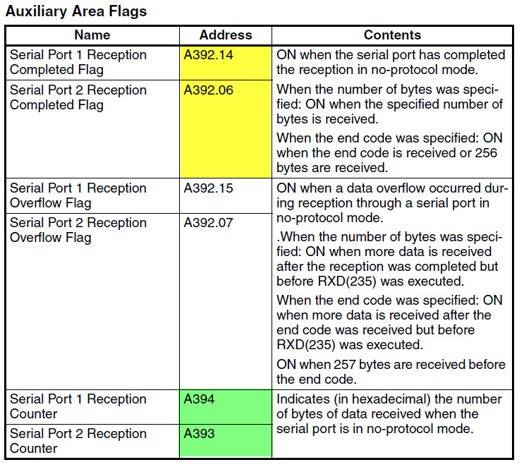
So, using port 1, it would look like this:
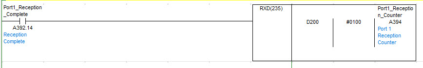
I arbitrarily chose D200 for the reception area.
-
I was trying to show you how I would set this up at least and I cannot find the EDS file. Can you attach it and I will share how I would do it? Of course that doesn't mean that it would work, if something is wrong with their EDS file, but I could show you how the setup should look at least.
-
Sergei makes a good suggestion. I might also set CR+LF as the end code and receive each part of the message separately (5 total messages, if I understand correctly).
-
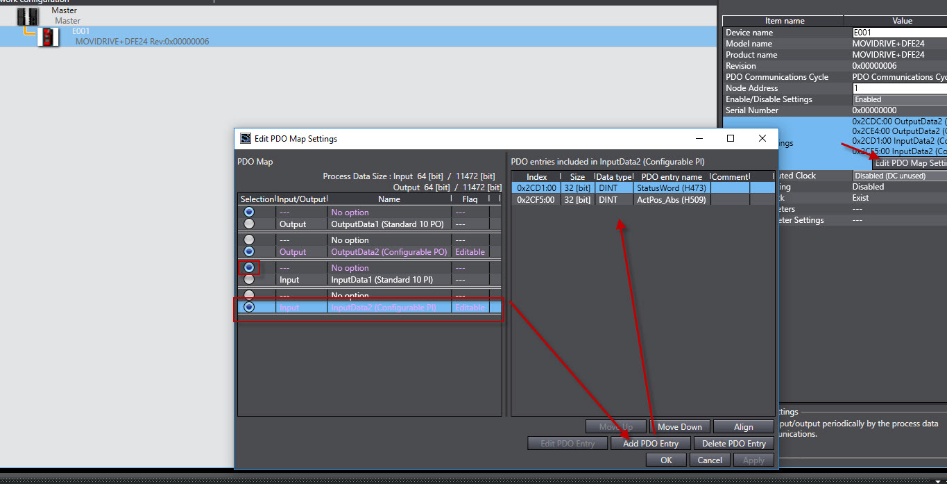
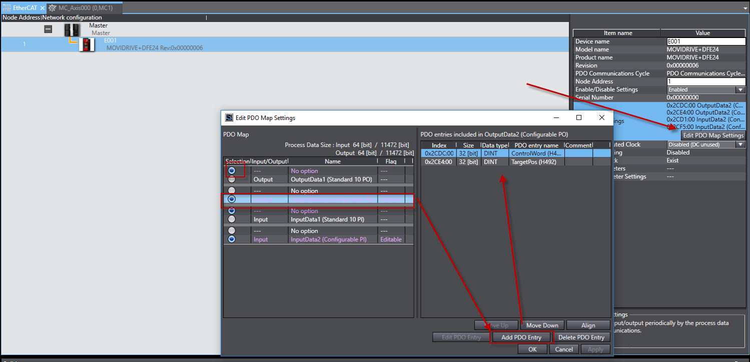
I modified the PDO map for the drive to look like this for the input side:
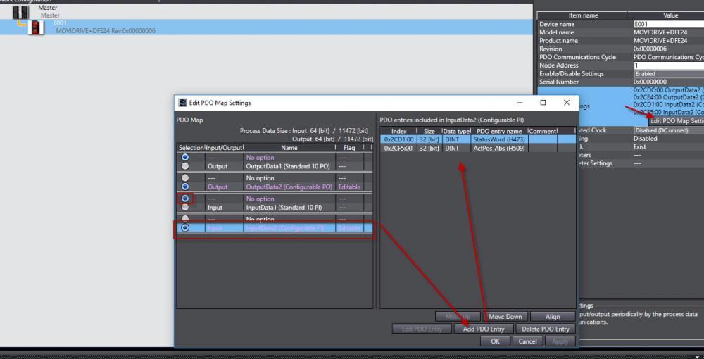
I am unsure about the ActPos_Abs being the correct selection as there are multiple options for actual position. You may need to ask SEW.
And this for the output:

I also enabled the distributed clock (right below the PDO Map Settings button).
And then I mapped them like this for the axis:

When I do this, I still get the same error that you were getting. So I kept digging. I noticed that SEW's Control Word and Status Word were DINTs (32 bits), so instead I mapped PI0001 and PO001 to those and removed the control word and status word from the PDO map. Then I attached those to the Axis settings like this:
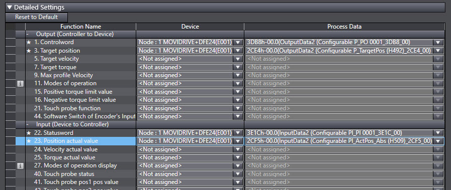
When I download that, the error goes away. Of course it will likely not work at this point, but it does show that the issue is that SEW's control Word and Status Word (both should be 16 bits as that is what WORD implies) are actually 32 bits. So (SEW, ha!), I would ask SEW what the deal is with 32 bit Status and Control WORDs. They may be able to somehow map one half of those 32 bits to both the PO001 and PI001 WORDs.
-
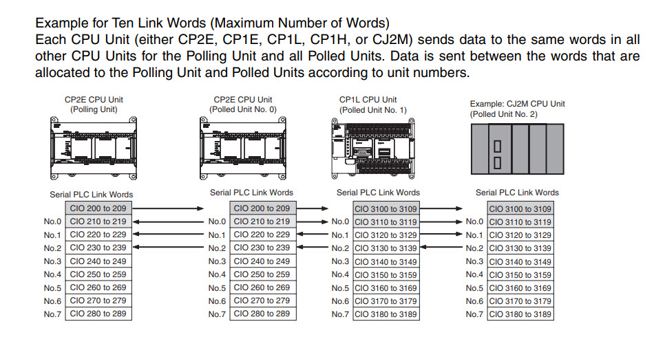
Quick tip on this subject: When searching the manuals, you will see it sometimes referred to as "PC Link" and other times as "PLC LInk". All of the helpful information can be found searching for "PLC Link" with respect to examples and how to set it up.
I think that your mistake is that you are assuming that PC Link unit 0 uses the first area (3100-3109 on CP1H and 200-209 on CP2E). It does not. That area is for the Master. Node 0 starts at 3110 and 210. So, your node #1 will actually be at 220 in the CP2E.
This example is taken from the CP2E Unit Software User's Manual:
-
That is a tough one. Do they need to be closer than 4mm (or perhaps it is 8mm if you need to account for 4mm for each axis) when jogging? If not, just monitor the commanded position (as opposed to actual position) and don't if the difference between the two is ever less than 4mm (or 8mm) then stop them.
-
Check out my response on this post:
-
You can update the firmware version in CX-Motion Pro under the tools menu when you are online. It is part of the CX-One Suite of software. I have a attached the 1.6720 firmware (newest listed in your list from the manual above). It is the newest that I have.
-
Many instructions use that flag. Due to this fact, the flag changes states many times during the scan of the program. Therefore, only the last state of the flag is shown when monitoring. This does make it difficult to troubleshoot sometimes. You can see the state of the flag at that particular rung by adding the flag to the rung (immediately below the instruction) and have it turn on a coil for a bit that is not used. Then look at the status of that bit to determine what state the flag is when it was executed at that rung. There is another discussion somewhere in here that talks about these flags. I will try to share it and provide a link for you.
-
-
I have v1.6720, as far as I know, that is the newest. What version do you have?
-
One correction: Each unit is allocated 100 words in the DM area beginning at D30000. So, D30000 + (unit number * 100).
Each CPU Bus unit is also allocated 25 words in the CIO area, 1500 + (unit number * 25). <--- I think @gtsuport is combining the two together.
-
I just tested this and am getting the same result as @OmronOmicron:
If I have this:
192.168.0.66
Subnet: 255.255.254.0
It works fine.
If I change it to:
192.168.1.66
Subnet 255.255.254.0
The PLC sets the IP Address to 192.168.250.66.
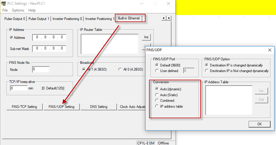
So, it is not just the fact that you are using a non class C Subnet, but rather that you are using the non Class C subnet and the FINS node calculation from the IP address / Subnet combo (see link in previous comment) creates a FINS node number that does not match the FINS Node number set in the PLC settings (below Subnet Mask). This appears to be the design.
1 person likes this -
@IO_Rack shared a link that may help. The controller should accept your settings and allow you to change the IP Address and Subnet to what you desire, however you may have issues connecting using FINS if you have something other than Auto (Dynamic) set for the FINS UDP conversion when you use a subnet of 255.255.254.0.
-
Is this a CP1L (with an adapter) or CP1L-E with a built in port? It sounds like a CP1L-E, but I just want to make sure.


Float Valve
in CX-Programmer
Posted
I am glad to help people. I will not just do it for them, particularly if they get an attitude.