

suresh_
MrPLC Member-
Content count
68 -
Joined
-
Last visited
Everything posted by suresh_
-
Is it true that Omron has discontinued ASICs based microprocessor in favour of Intel ATOM? Generally speaking, I cannot find precise information about the microprocessors used in OMRON PLCs, If someone could provide some details about this topic it would be greatly helpful.
-
hello Marco, clearly the manual is the reference N.1 however there is some learning curve and may be you need some guidance. As a start you need to know that AI Expansion Units setting has to be done via available OUTPUT channels in your PLC, in the same manner input AI readings shall be done via available INPUT channels. This is the main difference compared with an AI embedded in your PLC. However in your case, I see another Expansion Unit directly attached to the PLC so it will consume its own IO Channels and you have to take it into account when you are programing your AI module. Speaking of Expansion module, please note that they are channel consumer, AI/O or Boolean I/O cahnnel there is not difference, so if you have a module to the left of your AD42 keep in mind that this is consuming channels that you cannot made avaialble for other modules so you should study also this module manual. Finally, when you made your AI avaialble and converted into HEX you need to scale it in engineering units via SCL, SCL2 or APR. Experienced users prefer APR because is BCD free but is just matter or personal preference. Just in case, there is another similar issue in the forum so you may check it out.
-
my BCD to BIN CONVERTER View File here sinple logic similar to BIN function. Note:no need of error flag here bcs in case of input error, converted output is set to #0000 (on the contrary BIN function activates error flag bcs is keeping last valid value). Submitter suresh_ Submitted 03/23/22 Category PLC Sample Code
-
-
hello Benji, the basic concept is: once you set up your logic, you need to refresh it automatically every 365 days. First you have to set D0 that is control word for DT instruction and get rid of sec, min and hours. After that you have to define your control logic and register it to PLC activating W90.00 ( this can be done during commissioning or by the Client from HMI ) : clearly this has to be done automatically every 365 days. In the example given, today date is frezeed and MOV to D or (better) H register . To specify 365 days requirement you may ADD #100 to D353 (meaning increment 1 Year =365 days ) and compare it with present date in the DT instruction. After 1 year from today date W0.00 will be ON triggering whatever actions you need. After your task is done W90.00 need to be refreshed again so the new date will be freezed for the next cycle. To check your logic you have to start simulation, go to Clock section in the Project workspace, manually increment the date by 1 year ( actually few seconds less) and see, after few seconds, if DT will set ON its output or not. If your logic is different you have to set up BCD data you need and MOV it to register, increment it by 1year and send to DT function as usual: DT function will operate the timer accordingly. I hope it help.
-
hello Benji,I think you can easily fit this logic to your needs , however you have to decide if your customer should be allowed or not to adjust (or tapering...) Clock settings from HMI. Finally using H register instead of D can preserve your setting in case of persistent power failure.
-
hello Muhammed,the ladder seems fine to me so it is tricky, however may be there is wiring issue or may be the PLC is confused about Expansion AI CH you effectively are using: i.e. if you are using only CIO3 you may try to inform the PLC about this fact like below: MOV #800E 103 MOV #8000 104 You may also recall expansion error word A436 and see if there is an error there I hope it helps
-
Hello Muahmmad, I have seen your post just now. May be it can be useful for yout to check out my recent reply in this forum about a similar subject.
-
Hello Marco, based on AD041 I am familiar with, you may refer to attached screen shot. After that you may use SCL2 function (noting that numeric example in Omron manual is wrong ) to scaling your AI ND consume it in your program logic. Resolution is 6000 but full scale may change according to your input ( volt / mA) that has to be specified in PLC setting section. I hope it helps.
-
Hello Ben, you may use DT compare function e.g. is listed in the SS that is counting 365 days from today date but you may change it at your convenience. Once scheduled task is done you can refresh and start next cycle.
-
[PLC Sample Code] - my EXPONENTIAL INTEGRATOR (1st ORDER SYSTEM WITH LAG)
suresh_ posted a topic in Download Comments
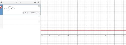
View File my EXPONENTIAL INTEGRATOR (1st ORDER SYSTEM WITH LAG) here integrating function from T=0 to T=2.5 with POWER SERIES and error correction. D250 simulates behaviour of first order system with lag. Submitter suresh_ Submitted 03/16/22 Category PLC Sample Code -
Version 1.0.0
11 downloads
here integrating function from T=0 to T=2.5 with POWER SERIES and error correction. D250 simulates behaviour of first order system with lag. -
my QUADRATIC SIGNAL INTEGRATOR View File here simple fucntion that calculates TIME integral of a quadratic signal with Coefficient (Real number). Error correction section is provided. Note: Input TIME and COEFFICIENT. Submitter suresh_ Submitted 03/16/22 Category PLC Sample Code
-
-
[PLC Sample Code] - my LINEAR SLOPE/TIME INTEGRATING FUNCTION
suresh_ posted a topic in Download Comments
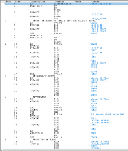
View File my LINEAR SLOPE/TIME INTEGRATING FUNCTION basic integrator provided with error correction section. Inputs are SLOPE * 1000 and TIME *10. No need of PIDAT so it can run on a PC. INTEGRATOR_02.cxp Submitter suresh_ Submitted 03/16/22 Category PLC Sample Code -
Version 1.0.0
6 downloads
basic integrator provided with error correction section. Inputs are SLOPE * 1000 and TIME *10. No need of PIDAT so it can run on a PC. INTEGRATOR_02.cxp -
my HELLO WORLD (Lorem Ipsum) View File here Hello World ( Lorem Ipsum) in CX programmer via String Data Type Submitter suresh_ Submitted 03/12/22 Category PLC Sample Code
-
-
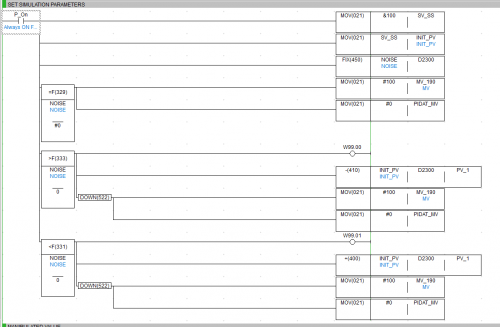
View File my FEEDFORWARD PIDAT CONTROLLER in this sample +/- NOISE signal affecting the Steady State is feeded to PIDAT controller to keep the process stable and reactive. Note: PIDAT function is not implemented in CX simulator. Submitter suresh_ Submitted 03/11/22 Category PLC Sample Code
-
Version 1.0.0
23 downloads
in this sample +/- NOISE signal affecting the Steady State is feeded to PIDAT controller to keep the process stable and reactive. Note: PIDAT function is not implemented in CX simulator. -
Math Floating Point numbers without Registers
suresh_ replied to Abdul Wajid's topic in CX-Programmer
Dear Abdul, let me add another info for you. If you decide to use variables, you can use MOV to input a FP as you do for Integers. To do that you need to generate your Variable ( eg TEST) in the symbol section, specify REAL type and associate to a register (D100 eg). After that you can recall TEST variable in your ladder with MOV instruction and manually input your FP or associate it to an AI as you wish. In this way you can input your FP for later on use usingf MOV. According to PLC set up and register you selected ( HR, DR,..) , TEST variable may be or may be not saved once you switch OFF and ON your PLC. I hope this clarifies. -
my 3X3 MATRIX OPERATOR View File simple algoritm for 3x3 matrix multiplication. Tot. Nos. N x N FOR loop will be required to do the math (9 in this case). Refresh every time one input value is changed. Reduction of FOR loops via nesting may be applied. Submitter suresh_ Submitted 03/10/22 Category PLC Sample Code
-
-
Math Floating Point numbers without Registers
suresh_ replied to Abdul Wajid's topic in CX-Programmer
Dear Abdul, as chelton pointed out, you may input a FP value directly and consume it on the spot if the consumer function allows a FP because not all functions do. Otherwise, when you write a FP value into a register to be manipulated later on, you cannot simply use MOV because MOV is not meant for FP assignment, so you have to find some turnaround to do this as I showed before. Otherwise you need to use ASCII string to FP that can be very tricky indeed. Bottom line, since OMRON is loose about data type ( bcs they are very concerned about backward compatibility ), there is no need to stress too much about data type, simply enter a FP and let the SW do the work for you. -
View File my FOR NEXT LOOP here a simple example of Array multiplication using a FOR_NEXT loop. It should be stressed that BREAK instruction is fundamental to operate the FOR NEXT loop correctly, on the contrary N: Number of loops ( #DADA in the sample file) of FOR instruction is not so important ( has to be <> #0 anyway ) . Submitter suresh_ Submitted 03/10/22 Category PLC Sample Code