

d4rkm4n
MrPLC Member-
Content count
54 -
Joined
-
Last visited
Posts posted by d4rkm4n
-
-
On 3/13/2024 at 4:04 AM, Crossbow said:4100 is a generic operation error... in your case it has nothing to do with a memory card or a network...
Look at the FIRST line of the error message... THE INSTRUCTION CANNOT PROCESS THE CONTAINED DATA. When it gives you a program name and step number, it's a program error.
The instruction it is highlighting is having an error with the input data... so what is put in via K4X460 does not work in the DBIN instruction... check the status of your inputs starting at X460 and see what it is trying to do. And look at the help for DBIN to see what about it can cause the 4100 error.
Thanks for your input.
I have checked the program and the input is coming from BCD signal from weigher.
I found no abnormality on the weigher side.
I also found as attached in the manual:
The error will coming "When values other than 0 to 9 are specified to any digits of (S)", what will causing this? The input 10 will always give numeric right?
Btw, also mentioned, error can be suppressed by turning ON SM722, if I turn ON the SM722, will the instruction still works?
EDIT: Just checked, if abnormal inputs from BCD, the (S) will in minus (-). But as per picture, current (S) value is 0.

-
Sorry for bumping old thread. I still looking for solution.
-
Not really familiar with VFD but is whole module fail or just a point?
Anything abnormal from 5 of those VFD?
I think isolator is also a solution, your system been running fine for 10 years then not even with new module. Probably something on your VFD.
Btw, I always wonder, what is the resistance reading indicate when we measure on intput/output terminal?
-
On 1/3/2024 at 8:19 PM, Ron_S said:D0 or DO?
However, the outputs can be supplied on the common terminal with 0V and 24V can be the common for the relays/contactors in the panel.
It's the practice in Japan and often Chinese machines. The S/S is just for input signals
Digital Output.
Is there any where I can study detail on this?
I just confused how the whole, output can send 0V.
Btw, I also wondering, how do I know the VDC value should I get at DO point when the signal is ON/OFF?
As for DI already clear, need to check which one is connected to S/S.
-
18 hours ago, Gambit said:Same for DO?
-
On 3/17/2023 at 4:05 PM, Gambit said:Which PLC are you using ? FX .. In that case it depeands on how the S/S is connected.
If you connect 24V to the s/s than you get an High signal when 0V is connected to the input.
If you connect 0V to the s/s than you get an High signal when 24V is connected to the input.Hi, sorry takes sometime to reply.
Yes, our PLC was FX3U.
So meaning the one connected to S/S will be common right? Is 24V is + and 0v is -?
Btw, I found the output also act the same way, when DO is ON, it give 0V and 24V when OFF. Is it also based on S/S wiring?
One thing I cannot understand, the DO give 0V when DO is ON but when we check contact at contactor (output receiver), it received 24V.
-
You can download S7 Graph from Siemens website.
Edit:
-
Hi guys,
Currently I use MCR to disable program and create a M direct to Y, and online change for each Y It a bit slow for online change to completed.
So, I wonder how to do loopcheck for let say 64 points DO?
I try to make MOV M100 Y0 K4 but not success.
Target to make M directly trigger a Y.
Thanks!
-
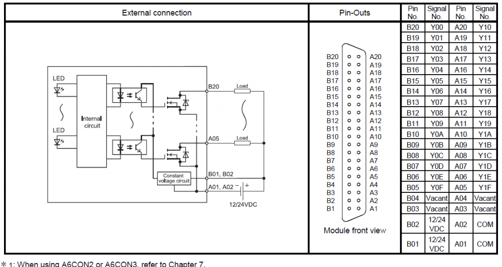
On 6/13/2023 at 7:33 PM, pturmel said:If really as shown (and there's no reason to think differently), those inputs are not convertible. They are sinking, with shared negative common. You will need another (different) module, or add an interposing relay.
Thanks. I thought the common can be separated as we have spare from A20 to A05.
End up install interposing relay.
-
Hi guys.
So I have a QY41P, currently signal is wet contact with 24VDC.
I would like to use same module but with dry contact 0V, is it possible?
I see there are 2 common termination provide but not sure how it was separate, from manual looks like it shared for all output.
Thanks!
-
FX1N
in Mitsubishi
What is your input pulse interval? Normal condition, the input will always pulsing? If abnormal input no pulse?
During actual test, does Y0 trigger?
-
Hi guys.
During trobuleshooting one of our machines, I found that some DI modules give 24VDC when contact is OFF and 0VDC when contact is ON.
Is there anywhere I can configure and change that setting?
Thanks.
-
On 1/23/2023 at 2:12 PM, Byri Manoj said:Hello everyone,
I am trying to "write to got" with simple objects like switches and lamps but when I upload the program through USB it shows "Error 402 communication timeout". The screen is not displaying any lamps. What to do? I tried writing to SD card and flash memory. The error persists whatever I do, please help me rectify this.
Did you able to read the GOT or do communication test?
-
Basically, you want a remote access to your PLC through internet?
Try go search for MCWorks and MXConfigurator.
-
7 hours ago, nehpets said:The K4 in the instruction represents 4 nybbles (group of 4 bits = nybble) therefore K4 signifys 16 bits
The instruction is moving Hex 10 into M60 to M75, (K4M60), as the binary pattern of hex 10 is 0000000000010000 then M64 becomes true.
Thanks!
How about H400?
Binary is 010000000000 , does it mean it was for M70?
1 person likes this -
Hi guys,
I come across a program with instruction
MOV H10 K4M60
But I cannot understand how this will turn on M64?
Tried to convert from H10 to binary (00010000).
Also there is MOV H400 K4M60 and I'm not sure which bit is trigger. I believe it was M65 but the binary is 010000000000.
Thanks!
-
I believe you need to check all PLC/HMI, see if any of them if connected/referring to network #3.
If I'm not mistaken, you could check at CC Link configuration, maybe for IO mapping.
Btw, which model of PLC?
-
Looks like something disconnect from the module.
Is your ENET module blinking? Try to ping the PLC.
-
On 10/19/2022 at 3:51 AM, Lambir said:Yes, because it is written in the manual. K1 means 4 bits. And as you can see from your example, it is valid also for D registers. Of course also for X, Y and M.
-AdobeAcrobat.png.06d3f6f65e8514ea72c2318819342357.png)
Thank you very much.
-
I have had an issue with FX5U before. The PLC wont power on.
I was told by our contractor, the PSU can be repair (change electronic part).
But luckily, the PLC power back on after we dismantle all the part and do air spray cleaning.
-
1 hour ago, Goran Vuckovic said:Nibbles not bits. K8 = 8 x 4 = 32
Thanks for your reply.
Why x 4? Any reason? Applied to D, X and Y as well?
-
Hi,
I found this instruction on this ladder and wondering how it is calculated?
From the right, I understand they compare value from M0-M31 to M300-M331 because they started next with M32/M332.
I thought it K8 * 8bit = 64 but it is not.
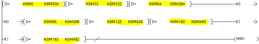
Thanks!
-
Thanks a lot!
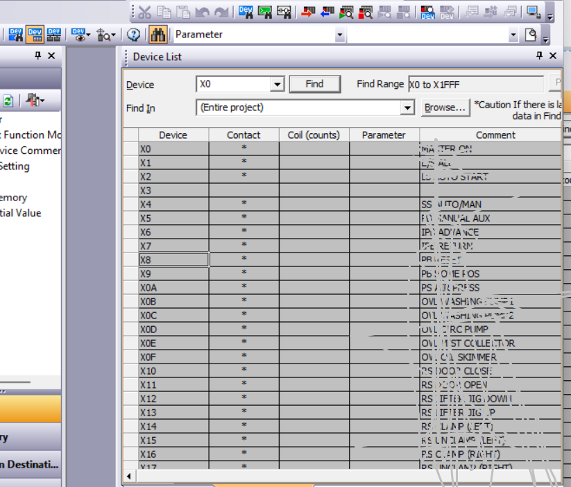
On 9/22/2022 at 4:03 PM, CangkeMan said:if u are using gxworks2 , try this Device List feature.
 On 9/30/2022 at 9:11 PM, Dave W. said:
Same with GX Works3 or use "Cross Reference"
-
Hi,
I was wondering, is there a better way to check for spare points beside searching for one-by-one in the program?
Thanks!

Q-Series - Operation Error 4100
in Mitsubishi
Posted
I will try to disable the error once the process is stopp, btw, how do I permanently ON SM722? Is it back to OFF if I power cycle or restart the PLC.
What do you think is the best way to debounce BCD value for weigher? I am afraid they are using the value to stop some sequence, I have not fully study the program yet due the writing looks so complex. =\