
86 files
-
Day-of-Week Calculation for SLC 1.0
By Chris Elston
This program was written for an SLC-5/03 processor. It was designed to display date time and day-of-week to a Panelview 550. It uses the 5/03's internal clock for the time and date and then calculates the day-of-week. Newer revisions of the 5/03 ca
2592 downloads
Updated
-
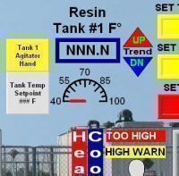
Temperature Trend Direction Flag
By Chris Elston
Operator wanted an easy way to tell if temperature was rising or falling in the tank. So without having to setup a full blown trend chart I came up with the "trend flag". If the flag or integer "Tank_1_Resin_Temp_Trend" was equal to "1" then the temperature is rising. If the flag is "0" then the temperature is falling. Easy fix with one rung.
2438 downloads
Updated
-
Production TAKT Timer - PLC Program
By AubergM
Our Improvement department wanted a way for the operators to know where they were in the process based on cycle times. I came up with this little jewel to alert the operator with a buzzer half way and < 30 seconds remaining. We look at # Made Hit an
1981 downloads
Updated
-
2 Button manual sealing bar
2 button operation for a maual sealing bar. both buttons must be pressed at the same time in order to complete operation. Good for keeping the operators hands away form the sealing blade.
2181 downloads
Updated
-
Day of Week + Week Number + Auto BST adjustment
By Snerkel
Calculates the day of the week.
Calculates the week number.
Auto adjusts PLC clock for British Summer Time.
Works with any SLC processor with a RTC does not require floating point.
2112 downloads
Updated
-
20-COMM-E Adapter Diagnostics
By Ken Roach
To rule out problems with data traffic to AC drives sometimes I ask a user to monitor the DPI Diagnostic Items in the 20-COMM-E interface. These can be read using Drive Explorer Drive Executive or the 20-COMM-E embedded Web page.
But the controller can also read these values with a little help from the 20-COMM-E User Manual and some ladder logic for messaging.
The DPI Diagnostic Object is Class 0x99. The Diagnostic Item value is Attribute 1. But what's the Instance number ?
The Instance number for Adapter items begins at 0x4000 (16384) and I am interested in Items 49 through 55:
Item# Name Instance # Data Size (bytes)
49 EN Rx Overruns 16433 2
50 EN Packets Received 16434 4
51 EN Rx Errors 16435 4
52 EN Packets Sent 16436 4
53 EN Tx Errors 16437 4
54 Last TCP Reset 16438 2 (Read Only)
55 Missed IO Packets 16439 4
This ladder example just reads those 7 values repeatedly. I could be expanded to cover multiple drives.
These values are all reset when power is cycled which is why I'm interested in having the controller read them instead of standing around looking at the software monitor all day or trying to have people read them before they cycle power to the drive.
1304 downloads
Updated
-
i_canoe's Best Sequencer
By Guest
I"ll post the simple version to make it all to easy. This is the base for nearly all my programs and I have used it for ten years and hundreds of systems. Just try and remember and service that convaluted program you wrote eight years ago you will
3343 downloads
Updated
-
Updated
-
PC Module Status
By Ken Roach
In applications where unreliable IP transports (such as wireless) are used some users report "flaky" Produced/Consumed tag connections and I/O connections over EtherNet/IP.
Rockwell never recommends wireless Ethernet for I/O but some users overlook this recommendation or install links that should be reliable enough but due to installation or configuration issues are not and need to be troubleshot with the participation of the control system.
This logic example is a diagnostic tool to provide a timestamp and duration for connection faults. It is written for a controller Producing data to another controller over EtherNet/IP but would work the same for a connection across ControlNet or the ControlLogix backplane or for an I/O connection.
The program was written using RSLogix 5000 v12.06.
Just putting the remote Controller into this Controller's I/O tree is enough to establish a connection; the Produced/Consumed tag (called Produced_Data on the producer side and Consumed_Data on the consumer side) is not strictly necessary.
I've used logic like this to find interference from motion controllers or heavy motor starters as well as microwave oven interference in the 2.4 GHz range. It's not a cure-all diagnostic tool but it can tell you when and how often a connection is failing.
This logic may be used in conjunction with the traffic analysis tool triggering example to capture data on an Ethernet network on both sides of a connection failure event.
1660 downloads
Updated
-
MicroLogix 1500 DNet MSG to multiple PF40
By Ken Roach
6-rung code example to read one parameter from multiple AC drives on DeviceNet.
2036 downloads
Updated
-
SLC CLOCK CHANGE FOR DAY LIGHT SAVINGS TIME
By Ken Moore
This logic will advance the system clock one hour on the first Sunday in April and retard it one hour the last Sunday in October.
After installing the day of the week counter will have to be set correctly.
2426 downloads
Updated
-
LONG DURATION PRECISION TIMER.pdf
By TConnolly
From time to time a long time base precision timer may be required. The SLC .01 second timebase timer is good for only 327 seconds. Cascading a timer and a counter together is undesirable as it will introduce a cumulative error into the time because of differences between when the time period
actually expires and when the timer is next scanned.
By running two timers in parallel we can maintain an accurate time reference from which to compute a floating point time with .01 second precision up to 32767 seconds. The first timer has a one second time base and it is the primary timer. The second timer has a .01 second time base and it is
used solely to compute the fractional seconds. By using a comparison to subtract one second from the .01 second time base ACC when ever it exceeds a full second we can maintain an accurate time independent of the processor scan time so long as the rung is evaluated more than once a
second.
2426 downloads
Updated
-
Complex numbers for Allen-Bradley
to apply the mathematics of complex numbers,<BR closure_uid_n926ba="1383" Pc="null">also on plc.<BR closure_uid_n926ba="1384" Pc="null">I send you some Add-On Instructions for dealing with complex numbers
this for RsLogix5000 and Siemens S7
1427 downloads
Updated
-
Daylight_Savings_CL
X By ward
This is a program to change the processor clock ahead one hour in April and retard the clock one hour in October.
2352 downloads
Updated
-
Solve system whit Gauss-Jordan
This Add-On Instruction Solve the equations System
whit Gauss-Jordan Reduction
In the matrix A [ i , j ] put the System of N-Equation.
In the vector b put the solutions
§§§§§§§§§§§§§§§§§§§§§§§§§§§§§§§§§§§§§§§§§§§§§§§§§
Example 1: Linear System 3 equation (X,Y,Z)
3 X + 2 Y - Z = 10
- X + Y + Z = -2
2 X - Y + 2 Z = -6
| 3 | | 2 | | -1 | | 10 |
X | -1 | + Y | 1 | + Z | 1 | = | -2 |
| 2 | | -1 | | 2 | | -6 |
Matrix A :=
Matrix[1,1]= 3 ; Matrix[1,2]= 2 ; Matrix[1,3]= -1
Matrix[2,1]= -1 ; Matrix[2,2]= 1 ; Matrix[2,3]= -2
Matrix[3,1]= 2 ; Matrix[3,2]= -1 ; Matrix[3,3]= -6
Vector b:=
Vector[1] =10 ; Vector[2] = -2 ; Vector[3] = -6 ;
Solution :=
Solution [1] := 1.0 ; Solution [2] := 2.0 ; Solution [3] := -3.0 ;
X = 1 ; Y = 2 ; Z = -3
§§§§§§§§§§§§§§§§§§§§§§§§§§§§§§§§§§§§§§§§§§§§§§§§§§§§§§§§§§§§§§§§§§
Example 2: Linear System 5 equation for resolve Polynomial 4th grade
exampl. Polynomial whit 5 points:
P0(-1,-1) ;
P1( 1, 3) ;
P2( 5, 3.5) ;
P3( 6, 4.5) ;
P4( 7, 7) ;
Write in the Matrix A [ i, j ]
Matrix A :=
Matrix[1,1]= (-1)^4 ; Matrix[1,2]= (-1)^3 ; Matrix[1,3]= (-1)^2 ; Matrix[1,4]= (-1) ; Matrix[1,5]=1;
Matrix[2,1]= (1)^4 ; Matrix[2,2]= (1)^3 ; Matrix[2,3]= (1)^2 ; Matrix[2,4]= (1) ; Matrix[2,5]=1;
Matrix[3,1]= (5)^4 ; Matrix[3,2]= (5)^3 ; Matrix[3,3]= (5)^2 ; Matrix[3,4]= (5) ; Matrix[3,5]=1;
Matrix[4,1]= (6)^4 ; Matrix[4,2]= (6)^3 ; Matrix[4,3]= (6)^2 ; Matrix[4,4]= (6) ; Matrix[4,5]=1;
Matrix[5,1]= (7)^4 ; Matrix[5,2]= (7)^3 ; Matrix[5,3]= (7)^2 ; Matrix[5,4]= (7) ; Matrix[5,5]=1;
Write in the Vector [ ]
Vector b:=
Vector[1] = -1 ; Vector[2] = 3 ; Vector[3] = 3.5 ; Vector[4] = 4.5 ; Vector[5] = 7
Solutions :=
Solution [1] := 3.27380234e-003 ; Solution [2] := 0.03363105;
Solution [3] := -0.56577414 ; Solution [4] := 1.966369 ;
Solution [5] := 1.5625005
§§§§§§§§§§§§§§§§§§§§§§§§§§§§§§§§§§§§§§§§§§§§§§§§§§§§§§§§§§§§§§§§§§
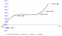
Example 3: Linear System 6 equation for resolve Polynomial 5th grade
example. Mototion Interpolation whit Polynomial
whit 2 Points :
P0 (Time0, Position 0) Start point whit (Velocity 0, Acceleration 0)
P1 (Time1, Position 1) End point whit (Velocity 1, Acceleration 1)
Write in the Matrix A [ i, j ]
Matrix A :=
X0 = time0 ; X1 = time1
Row1 X0 ^5 + X0 ^4 + X0 ^3 + X0 ^2 + X0 + 1 (Position P0)
Row2 5 * X0 ^4 + 4 * X0 ^3 + 3 * X0 ^2 + 2 * X0 + 1 + 0 (Velocity P0)
Row3 20 * X0 ^3 + 12 * X0 ^2 + 6 * X0 + 2 + 0 + 0 (Acceleration P0)
Row4 X1 ^5 + X1 ^4 + X1 ^3 + X1 ^2 + X1 + 1 (Position P1)
Row5 5 * X1 ^4 + 4 * X1 ^3 + 3 * X1 ^2 + 2 * X1 + 1 + 0 (Velocity P1)
Row6 20 * X1 ^3 + 12 * X1 ^2 + 6 * X1 + 2 + 0 + 0 (Acceleration P1)
Vector b:=
Vector[1] = Position P0 ; Vector[2] = Velocity P0 ; Vector[3] = Acceleration P0 ;
Vector[4] = Position P1 ; Vector[5] = Velocity P1 ; Vector[6] = Acceleration P1 ;
Interpolation Polynomial Position :=
Position := s1* t^5 + s2* t^4 +s3* t^3 + s4* t^2 + s5* t + s6;
2087 downloads
Submitted
-
DnetExample
By tjmurf
A simple example to extract the error code and the device address from the 1747-SDN scanner.
This is a somewhat modified version originally from a AB technote which I can't find.
I used this for an HMI display. The last line is to mon
1955 downloads
Updated
-
1771-SDN Diagnostic Display tabulator
By Ken Roach
Makes a table of the "diagnostic display" values that scroll across the 1771-SDN indicator.
1538 downloads
Updated
-
Real to Fraction
Add-On Instruction Float to Fraction FTF
this Add-On convert a real to Fraction.
Add Documentation inside the file.
Good work.
1743 downloads
Updated
-
RND LINEAR CONGRUENTIAL GENERATOR Casual Numbers
A Linear Congruential Generator (LCG)
Represents one of the oldest and best-known pseudorandom number generator algorithms.
1365 downloads
Updated
-
Dryer- Basket safety and Forward/Reverse
By simsrjr
Thought I would put up a easy code using Micrologix controller that can be converted to an easy timer program I used this for work hope it helps. (Note I also have a short version if interested)
884 downloads
Submitted
-
TShark Triggering
By Ken Roach
This is a writeup and two examples of using a ControlLogix or an SLC-5/05 to trigger the TShark IP analysis program on a PC using the SerialKeys feature of Windows.
I am placing this file on the MrPLC website both for sharing and so I can find it again when I need it !
1153 downloads
Updated
-
Read Monitoring Parameters from E3 with SLC-5/0x
By Ken Roach
RSLogix 500 routine to read the first 20 parameters from an E3/E3+ overload relay on DeviceNet with an SLC-500 controller and 1747-SDN. This example uses the new DeviceNet Explicit Message (DEM) instruction introduced with OS302 Series C FRN10 firmware.
The 21st parameter is also important but will almost always be part of the I/O connection so we're only reading 20 parameters which fits more snugly into a data array.
This routine only reads from one E3+ device at Node 3 on the network.
1253 downloads
Updated
-
Save Version 2.0
By Chris Elston
Same as the Save below but with Comments on all Rungs. Save Timer Program using Indirect Addressing in 4 Rungs.
1808 downloads
Updated
-
Save
By Chris Elston
Saving x number of Timers or Data in four rungs. Example uses 12 Timers saved in N7. Then Move values from the N7's to the T4 Preset. The N7 values being moved into the T4 Preset can be different from were the T4 values were moved into. Not valid for
1381 downloads
Updated
-
AB DINT_to_ASCII_Hex
By twstevic
A routine to convert a DINT value into HEX and then an ASCII string.
400 downloads
Submitted