Search the Community
Showing results for tags 'the program in controller'.
Found 114 results
-
Good day sirs, i am a newbie at this motion controller setting. I would kindly like to ask for an assistance from all of you. i copied all the necessary data that i have on this project. I installed the wiring correctly i am able to Jog the servo motor. But when i try to Jog the motor Using GXWorks 2 i wasn't able to do so because its not showing any movement on the Mr J4 and the motor it self. is there any settings that i should have change? thank you for the time if you will need any information i am willing to give it thank you I have also attached the GXworks program and the servo conifiguration Please help me thank you project 1.gxw Servo 1.mrc2
-
Hi All, I am new to the forum and new to programming PLC and like every newbie I have a lot of questions - Brief History of me - I had been a Manufacturing Technician for 20 years and recently got my BS on Electrical Engineering and now working as an Equipment Engineer. The main reason that got me interested in PLC's is my degree, the field that I would like to get into and a recent problem that arise at work. My experience with PLC is very small in programming, some in TS I/O- However I had been studying by my self to the point that I built a test bench to understand it better and in the future create different project for learning purposes Currently I am putting together a tool Alarm delay program - Basically my exhaust sensors trigger an alarm (input signal turns OFF) before its send the signal to my tool for abort, I want to create a different Alarm which will cause a different response from my tool and delay the original Alarm by 10 min and then trigger the original Alarm - PLC = Panasonic FP0C14RS Reasons: Create a different Alarm: The response from my tool to this alarm will allow me to return my material back from the tool and put it in a safe spot. Delay the Alarm: Use a timer to perform this tasks - This the time that approx. it takes the to return the material. Trigger the original Alarm: I need to know which sensor was the problem in order to properly TS- So after my timer is complete - I want to know which sensor created the original Alarm My Current problem: I created the LD program, and while the original alarm stays OFF the program works fine - but since my exhaust sensor are always on - If my original alarm is trigger for a few seconds, just enough to start my Delay Alarm: I dont have a way to know which sensor trigger after my Delay(Timer)is complete, I reset my relays in order to be ready for new alarm. Please provide feedback to my program - I know currently is not the best way or efficient way to do this and there are better ways, but my plan is to get it to work and then later revisions improve the way the program can be written Thanks in advanced for your feedback and help Exh_delay_inv_rev1.pro
-
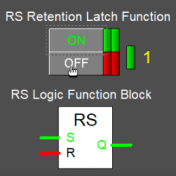
Hello everyone, I want to know why the Y172 coil is ON / logic 1? whereas contact SM1 is worth OFF / logic 0? can anyone explain it to me ?
-
Hello.. I have hmi Proface GP-4301TW, USB type B cable and ethernet cable. I want to transfer the program to the hmi but I cant. When I turn on the power of hmi, a series of test appears and finally it looks like the photo below and I cant enter the offline menu.. can anybody help me to solve the problem?
-
Respected Friends, Good day. I face a serious issue please help me to fix the problem. We have a 1756-L55/A controller with 1756/M13 A memory card. after 2 or 3 months the program washout and the LED status on the controller are following 1. RUN --- SOLID GREEN 2. I/O--- OFF 3. RS232 --- SOILD RED 4. OK --- SOLID RED 5. BAT-- OFF 6. FORCE-- OFF At that time CONTROL NET MODULES OK Light for Chanel A and Chanel B are also blinking and communication not established via control net and serial port AB-DF1. I switched off the power supply and after 10 second again power up the controller then OK LED becomes solid green. i download the program and its run fine. But the problem is still there. In the controller properties the major fault shows TYPE 01 [ POWER UP FAULT] CODE 60 [NON RECOVERABLE FAULT] what are the possible reason for wash out the program from the memory? At that time version 16.03 firmware installed and the rslogix program convert from version 10 to version 16.03. Is 1756 L555/A with 1756/M13 A support the version 10 firmware? i ask because the original program is in version 10 if its supported then i update the firm ware and download the original program. Hope you will help me in this issue. Regards
-
Please,if anyone has a working program (.stx).I need it to test a PL7 JUNIOR software
-
Hi, In conception phase we currently use GXWorks to upload programs to PLC (L-Series). In production mode, for different security reasons we would like to automate this transfer so that the operator does not access directly to the program. Do you know any tool allowing this by using command lines and not GXWorks UI ? (GXWorks does not seem to be "command line" friendly As a POC I have automated the GXWorks UI in C# (by simulating menu or buttons clicks) but I don't find it reliable (what if an unexpected popup "pops" ? ). PS : I am a totally noob in this PLC world so maybe I missed stg in the docs ...
-
A machine was bought at auction which included PLC-5/15 module. It did not come with a backup of the program. Our maintenance technician said the program would not load and turned the module over to me (IT). I notice the battery was installed in '92 so am assuming the program is lost. Is their any internal memory or last ditch effort i can attempt to recover the program from this module?
-
Hi Guys! You can read my problem below, if anybody can help, please do it. Thank you. So, I have 4 knife. You can set the cutting width for each knife separately. The problem is, there is a lot of size. There is an example: No1 size: #1: 20 mm, #2: 25mm, #3: 30mm, #4: 25mm (#1=Knife1.......) No2 size: #1: 22mm, #2:24mm, #3: 32mm, #4: 27mm What is make the problem more difficult is There are plenty of type code too. Like X1, X2, X3, Y1, Y2, Y3 ..... This is the main material code. and you can choose the belogging size. So you can select for X1 to No1 or No2 ... but you can select for X2 to No1 or No2 or any sizegroup you want. I can solve it with a lot programming, like deal every possible situation ... but there is a lot time .... :S There is a touch panel where you can set the values. Anybody have another idea for this problem ?
-
We have a QSeries PLC. Q25HCPU. We also have a PLC program. We found that the address registers (also known as device addresses) attain a z-value added next to it - automatically over time. We are not sure why this is the case. Nonetheless, when these values get added (by the PLC - not the engineering software), some of the functions in the PLC doesn't work. We found that by formatting the CPU, and reloading the program, allows for the system to work again (temporarily) for a few weeks, up until this problem occurs again. This problem occurs across various CPUs (eliminating the potential for hardware problems. These z values can be seen when a program comparison is done. (see attached file). The questions become; 1. What is the function of these values? (why does the PLC add them? 2. How can they be permanently removed?
-
Hello i'm new in all things about plc, i do a project for school and i use a festo fc 34 plc. The plc is programmed via serial port RS232 my pc not support a serial interface and i use a RS232 to usb adapter. when a try to download the program to plc give me a error: "ERROR: Cannot access controller". What i do wrong. Thank you in advance and sorry for my English. Have a nice day.
-
All, I am using Keyence CV-X422A vision controller for my application. It is interfaced with Siemens S7-1500 PLC on PROFINET. I am able to communicate with Vision controller through PLC logic command and status IOs. There is some communication issue in updating the o/p values from Camera Controller. I have tried with & w/o Handshake Mode with these settings. The camera display shows the reject but camera never turns ON the NG Status o/p. I tried different things told by Keyence Tech support but none of them worked. He told me to have you enable the “Result ACK Flag” in the bit allocation area and send a signal to it. Then trigger it again with a no good part and see if that fixes the issue. I tried setting the “Result ACK Flag” to 1 after I get the “Command Complete Flag” for the trigger signal that I sent. Sometimes this works but still it is not reliable. Do I need to send only a pulse to “Result ACK Flag”? Anyone here has ever faced similar issue? Thanks for your help. AP
-

PLC iQ-R R04CPU Socket TCP/IP communication via build in Ethernet port program example
ALMAR posted a topic in Mitsubishi
Looking for Socket TCP/IP communications program examples for Mitsubishi PLC iQ-R R04CPU using GX Works3, to compliment the Mitsubishi Ethernet manual Socket commands instructions. Unfortunately, the manual is missing real application ladder logic illustration examples of these commands. For example, the Socket Open Connection command, does not describe in what order or format to enter the IP Address. For example, to enter IP Address 192.168.1.100, does the most significant octet 192 is entered or stored first in the lowest memory storage register (Big Endian format) or does the least significant octet 100 is entered or stored first in the lowest memory storage register (Little Endian format)? I am trying to write a simple Socket TCP/IP communications command that will write about four registers from an existing Mitsubishi PLC R04CPU (Socket Client) to an Allen Bradley PLC ControlLogix (Socket Server). . -
Hello, I want to regulate the temperature by a thermocouple type T with an OMRON control module TC001 / 2/3 and a CJ2M CPU14 series PLC using CX-Programmer as a programming environment. Could you provide me with an example project? Thank you for your help.
-
Modbus TCP/IP communication with controllogix redundancy
Rasu posted a topic in Allen Bradley / Rockwell Automation
I'm using Controllogix L61 redundancy system as a slave with DCS using ethernet tcp/ip socket programming. The communication between master and slave will fail after a switchover. Kindly give solution for this. Thanks and regards, Rasu -
Hello, I am working with e5cc-t programs, for heating application. I need to find a way, to start program, when temperature reaches set-point of first (no. 0) segment. I think that, there should be some kind of setting, but i cant found it.. I've done this with PLC, but this is not an solution for this application. in conclusion: After program starts, it has to reach set point temp, and then hold temperature for certain time.
-
Hello, is there a way, to edit E5CC-T temperature controller internal program, using CP1L-EM PLC, connected to temperature controller via rs-485 communication? I can't find any information about doing it. I know that i cat change these programs, using CX-Thermo, but that is not an option. I need to do that, using only PLC..
-
Version 2.0.2
808 downloads
free HMI/SCADA program WebN Server 2.0 (freeware) * manual & program download site : http://www.netran.co.kr * Web-N Server 2.0 (freeware) - PLC interface demo video : https://youtu.be/MuOFMwK7Qqs* Android phone app download : https://play.google.com/store/apps/deta ... .en2&hl=en- Windows 7/8/8.1/10 x64, .NET frameworks 4.6 over - Mult-Language (tool language, view page language) - PC monitor, Web browser monitor, Smartphone monitor - (Design once and monitor on multiple instruments) Unlimited number of tags Unlimited monitoring time 1,024 concurrent connections Unlimited upgrade Unlimited connection of equipment (PLC, DCS, DDC ..) Unlimited app push message No Software fee No installation cost No registration fee No license fee No cost to use No upgrade cost Free Redistributable -
[Free Utilities] - freeware HMI SCADA program Web-N Server 2.0
webn posted a topic in Download Comments
free HMI/SCADA program Web-N Server2.0 (freeware) View File Program download site : http://www.netran.co.kr Web-N Server 2.0 - video for PLC interface demo : https://youtu.be/MuOFMwK7Qqs - Windows 7/8/8.1/10 x64, .NET frameworks 4.6 over - Mult-Language (tool language, view page language) - PC monitor, Web browser monitor, Smartphone monitor (Design once and monitor on multiple instruments) Unlimited number of tags Unlimited monitoring time 1,024 concurrent connections Unlimited upgrade Unlimited connection of equipment (PLC, DCS, DDC ..) Unlimited app push message No Software fee No installation cost No registration fee No license fee No cost to use No upgrade cost Free Redistributable =============================================== Submitter webn Submitted 08/29/17 Category Free Utilities -
it possible to get the program backup form plc fx2n 48mr and roster it in 3u-48mr
hatemmorsy posted a topic in Mitsubishi
it possible to get the program backup form plc fx2n 48mr and roster it in 3u-48mr -
AB 5/04 vs Panel Mate 1700 Replacement
Jim Custom posted a topic in Allen Bradley / Rockwell Automation
I'm making this thread, continuing from my previous one (Newbie Screwed Up) where I received tremendous help from those on this forum. I now have the AB 5/04 working, but the Panel Mate 1700 doesn't seem to communicate with the 504. The HMI connected to this brick is a Cutler Hammer Panel Mate Pro 1700. It lights up, the touch-screen buttons somewhat react to touching (might take a few strokes to react), but the functions do not react with the 5/04. I called the equipment manufacturer, and they basically said it is all obsolete equipment, no longer supported, etc. and we are SOL. But, for a mere $100K, we can send the unit back, and they'll install all "modern" control units !! Not an option. I get it that the unit is 10+ years old, but has very low cycle times on it. (maybe 400 hrs) It's my understanding that the HMIs are just that....a means of the operators telling the PLC what you want it to do. So, my question .... is there an off the shelf software package that would emulate the Panel Mate 1700? All I need to "control" is to advance or retard two sets of heat seal rollers (via PacSci stepper motors), actuate two separate hole punch solenoids, and an air solenoid for a knife....it's basically a packaging machine. I do have a program called PMConfig , but I don't see any communications buttons or icons in that software, just screen shots of what shows up on the HMI, icon selection, change fonts / colors, etc. So, I'm looking for a resolution to make new(er) HMI (or even just a cheap a$$ laptop) with affordable software, and easy interface to communicate with the now functioning 5/04. Thanks for the input. -
Trouble Wiring a Simple LED with a Micro820 Controller
Anthony Blanchette-Potvin posted a topic in Allen Bradley / Rockwell Automation
Hi everyone, Recently, I started working with the Micro820 Controller Embedded I/O. My project is simple : when the output _IO_EM_DO_00 is set to true, an LED light turns on. But, even though it's super simple, I can't make it work. Here's my setup. If you need more information, feel free to ask anything ! -
Hi Here's a question I'm about to ask Omron.. as soon as I can figure out who to ask.. It's complicated asking support.. their web email form doesn't make complex questions easy. Here's the question: Can the NJ CPU program a LinMot linear motor to make the "Random Sea"? The NJ has a mixed protocol.. Ethernet/IP and EtherCAT (CoE), and claims to be a "Motion Controller". I doubt Motion Control is available on it's Ethernet/IP line.. but the EtherCAT might be another story. Certainly The Omron NJ is a Motion Controller for Omron NJ series drives.. However, how well does it work with LinMot? Here's the curve. Imagine a LinMot Linear motor continuously moving, never really stopping, following a real-time, mathematically generated curve, moving positive then negative, at random frequencies and random amplitudes. Almost never repeating a motion sequence. looks something like this: Yet, after a while the motion history fully represents the spectral distribution of energy on the surface of the ocean. Spectrum analyzers can display it, and mathematics can define it.. I just have to make that sea in a model scale… (Time scales by the square root of the scale factor) And keep the water in the tank: https://www.youtube.com/watch?v=SQd6YzBWVvI The big question is: Can the Omron NJ get a LinMot Linear Motor to do this? … LinMot thinks YES.. but, isn’t sure. Yes there are ways to “connect" LinMot to The NJ.. EtherCAT (CoE), Ethernert/IP but… there is nothing in the LinMot drive that can create or store a predesigned Random Sea .. Only a Motion Controller, generating real time motion commands, by running mathematical equations, "on the fly” can do that. If the NJ is a true “Motion Controller”, and the LinMot C1250-DS-XC is implemented as an “axis” by Symac Studio, which it is… Then, there may be hope. Closed loop, PID feedback remains with the LinMot drive, with special settings in LinMot Talk … Homing might have to be done with the NJ .. or by Digital I/O’s What do the Omron experts out there think? Can this be done? Thanks much, Regards, Michael
-
Socket communication with Micro820
Anthony Blanchette-Potvin posted a topic in Allen Bradley / Rockwell Automation
Hi everyone ! I have a little project wich involves communication between two Micro820 controllers via TCP/IP. To do that, I started to work with TCP/IP socket. Within CCW (Connected Components Workbench), I tried to create a new socket instance using the instruction SOCKET_CREATE and set the socket address to 127.0.0.1:21. Basically, my computer through the FTP port. The problem was that it couldn't create a new socket instance (error variable is set to TRUE and status is set to 4, wich I don't know the meaning) because I didn't have a server-side application that listens to TCP/IP socket requests. That said, I found an open source application called SocketTest that listens for TCP/IP socket requests on a specified IP address and port. So, I started a listener on the following address : 127.0.0.1:21, but the error variable is still set to TRUE and status is still set to 4. So, my questions are : Is my IP address OK ? Is my port number OK ? What means the status code 4 ? Is SocketTest doing what I think it does ? Do I need to do something else before using the SOCKET_CREATE instruction ? Thank you in advance for your help !