Search the Community
Showing results for tags 'scaling instruction'.
Found 44 results
-
I am noticing a problem where i am using MOV instruction and writing literal text into source and String datatype in destination. It works fines in one program but doesn't on another it show an error Invalid Data Type. Argument must match Parameter Data type. I know what the error is and why but my question is why is it working perfectly fine in 1 program and not on another.
-
Hi guys, I am having difficulty in understanding and implementing the scaling of 32 or 16 bit binary data using Mitsubishi DSCL2 instruction. I just don't understand what to pass in its parameters particularly s2 parameter. I tried many variables but I get errors. Please can someone provide an example how to implement that and scale any float no, for example 1200.00 to 100.00 using this instruction with output scale 0-100 being 100 at maximum for the sensor value of 1200.00 I am attaching pdf for DSCL2 instruction taken from Mitsubishi manual for help. and the error I am getting on my melsoft. instructions_manual.pdf
-
Hi all I need to view a project in instruction list format on Mitsubishi GX Works 2. On GX developer the shortcut is Alt + F1 or View tab then press instruction list. Thanks
-

1734 IE8C 8 Channel Analog Input scaling
jpratik92 posted a topic in Allen Bradley / Rockwell Automation
Hello all, I have a temperature sensor with a reading range of 10F to 212 . The input card I am using is an Allen Bradley 1734 IE8C 8 Channel Analog current input. The current input values are 4-20 mA. Currently I have my raw low at 4000 and raw high at 20000. Can anyone explain how do we go about selection of this values ? I found these values in the configuration tag of the input card properties. Thank You -
I have plc mitsubishi A2USHCPU-S1 and there is already a program in it. The problem is, the analog input data doesn't want to be saved. How do i find the analog address instructions? Can anyone help?
-
Hi, I'm quite new to the PLC programming, I saw this delay input in one of the videos, that automatically switched to 1 after a set time, it wasn't a timer, just an contact input with time delay
-
Looking for information about an APR fuction for analog output. Thks
-
CP1L-L14DRD CP1W-AD041 Trying to scale an input 0-10 VDC = 0-10000 millimetres. My source word changes value but my D100 word does not and I get no change in the result. I have a SCL3(487) D100=0000/0 offset D101=1770/6000 X D102=2710/10000 Y D103=2710/10000 Max D104=0000/0 Min Any ideas?
-
Hello there, Today i have commissioned my first project with OMRON make PLC. Model: CP1L-EM40DT1D. (CX-Programmer) I have 2 built in 0-10V Analog Inputs on the plc. for analog input no-1 i get the digital value of 0-1000 in specific plc register address corresponding the 0-10V. (Factory setup) But today on site, i have noticed that some miner value of 0 to 50 is always coming and fluctuating very fast in that register, however the transmitter are genetaring 0.0V only (I have checked using digital multimeter with high precision) PLC and Transmitter are already grounded and all the cable connections are tight as well. so how to overcome this high fluctuating value ? is there any setting to filter the input ?
-
I have a problem trying to scale a floating number coming from an HMI to a value to use on PID instructions.My problem is on the scaling instruction.Whenever i try to run on cx simulator it gives me an error My setup of the scale parameters are (using SCL3(487)) D616 #0000 D617 &350 D618 #FFFF D619 #FFFF D620 #0000 My ladder to use the float number is: *F(456) Value +10,0 D2120 FIX(450) D2120 D2062 SCL3(487) D2062 D616 D2072 The error that throws is 0x80F0 Thanks in advance for any help PS Also tried all Scaling instructions.I think my problem is the setup of parameters for scaling instructions
-
Hi there! I recently discovered this forum and I find it pretty useful for sharing and learning about PLCs. The thing is I'm trying to make a Stack using the SSET(630) instruction in a CJ2M PLC. Reading Omron's W340 manual I saw that PLC memory address for the different stack channels is represented as "00010000" to "0001000F". So, in order to set the last stack word address as well as the pointer's address, how do you know those values? Or am I just misunderstanding something? Thanks in advance! Edit: Solved, the definition of the stack was wrong!
-
Hello Expert, I've problem regarding Instruction RS2. I can receive and send data, but my problem is each time I send data it will always add 0 at the back. I define array data for sending: POU_01/DATA_SEND[0] 769 00000011 00000001 H0301 -- #0301 -- Word[Unsigned]/Bit String[16-bit] VAR D2235 %MW0.2235 -- POU_01/DATA_SEND[1] 0 00000000 00000000 H0000 -- #0000 -- Word[Unsigned]/Bit String[16-bit] VAR D2236 %MW0.2236 -- POU_01/DATA_SEND[2] 2560 00001010 00000000 H0A00 -- #0A00 -- Word[Unsigned]/Bit String[16-bit] VAR D2237 %W0.2237 -- POU_01/DATA_SEND[3] 50637 11000101 11001101 HC5CD -- #C5CD -- Word[Unsigned]/Bit String[16-bit] VAR D2238 %MW0.2238 -- Data receive on Serial Terminal : "01" "03" "00" "00" "00" "0A" "CD" "C5" "00" ==> "00" last value I tried to figure out how can it get there ? I already check for terminator character already set off. I use channel 2 using FX-485-ADP-MB. I set my serial D8420 ==> "0C81".
-
M221 & SoMachine Basic - ANALOG INPUT SCALING
horvatmiha posted a topic in Modicon / Telemecanique / Schneider Electric
Hello! I am new at PLC programming. I am using TM221CE16R PLC with TM3AI8 analog input module and SoMachine Basic v1.6. I am trying to scale analog input value. I am using 4-20 mA pressure sensor. I managed my wiring so that I get raw values in SoMachine Basic. But I don't know how to scale these values to usable values. My sensor works in range 0 - 16 bar. What is best way to get values? Is it PID function block or multioperand function block using equations to get range 0 - 16? I will appreciate your help. Thanks in advance! -
A little background information here, I am trying to create a moving average so I accomplished it with the code (imaged attached) The problem i am having is the AVE instruction error bit goes true. it leaved me with a result of 1.#QAN I did some googling and it said this is typically done when dividing by zero?? so i added a NEQ to 0 prior to loading the array. then it happened again. so i put the error bit in front of the FFL so it will stop loading the array when i get the error bit so i can see what values are in the array when it errors out. Has anyone else had this issue and what could you do to resolve it? I haven't had any luck find something that points me in the right direction. Thanks in advance for your help.
-
Powerflex 527 rotating after MSO instruction
Jiggadoo posted a topic in Allen Bradley / Rockwell Automation
I am controlling the powerflex 527 drive with MSO instruction, first setting the drive on and then running the motor with MAJ instruction. After MSO instruction, motor is rotating about 2 sec and then stops to wait the MAJ. I have not find any solution for this. My configuration is frequency control, no feedback, sensorless. One hint i found from the rockwell pages but it did not help me. Rated slip speed is set to zero. -
Hello everybody, I have the following situation: I use the MAM function to move a servo axis; It also moves and stops correctly when the condition before turns flase. The result is actually good, except that sometimes a readjustment takes place (but only disturbs as I said sometimes). I have been sitting in front but didn't notice anything, only the Operator meant that this happens sometimes Now I would like to know how this can be stopped. Thank you What information do you Need to help me further
-
Version 1.0.0
201 downloads
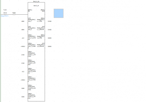
FB used for Built In Analog Inputs of CP1L-EL/EM With Scaling Set Up Included Demo_Built_In_v1.bak Demo_Built_In_v1.cxp Demo_Built_In_v1.opt -
View File CP1L-EL/EM Built In Inputs FB used for Built In Analog Inputs of CP1L-EL/EM With Scaling Set Up Included Demo_Built_In_v1.bak Demo_Built_In_v1.cxp Demo_Built_In_v1.opt Submitter MPOLITIS Submitted 07/22/19 Category PLC Sample Code
-
HEY, I'm kinda working on my own label machine and i am stuck on deriving its speed. I have already set the interrupt and acceleration parameters. but the problem i am facing is that i can't understand the ddvit's output pulse and output frequency relation to speed. If you guys know something, please do help. thank you,
-
Hi Guys! I have a problem. I have a leaser sensor, I already set the sampling frequency to 0,1 s. So 1 second I will get 10 data. I need to use the average of the datas. My problem is I dont know how can I solve that, after the 10. data every new data I have to recount, the last 10 data's average. I think maybe I have to use the FFL instrucion or something like that. I need to solve this problem in ladder diagram. I use RS-logix 5000 software. Anyone can help me? Unfortunatelly I havent the the software, so I cant show you what am I think. Maybe the sliding window solution is the right, or is it not related to this? Im a bit confused.
-
Hi group! I am struggling to figure out what I am doing with the Limit instruction (ZCP 088). I want to turn on a permissive if the compared word is between 1 and 12. Rockwell makes this so much easier!!! It looks like my "=" instruction is not correct but this is how they show it in the manual???????
-
hi there. i am using FX2n-4AD for measuring the volume of tank in litres. The problem is that litres tank can hold is 10,000 . and card resulation is max 1000 digital value for 20ma. so conversion factor 10, 000 / 1000 = 10liter for one digital raw value . which is much more as program will read for multiple of tens factor.. can any other solution for this problem with the same hardware
-
Logix 500 math instruction with Decimal Point
jimmy689 posted a topic in Allen Bradley / Rockwell Automation
Hi my problem may have a simple solution but i cant work it out. I need to use the Divide function but it wont let me use a decimal point in either Source A or Source B. Is there a way to use a decimal point in Logix 500 Math instructions? Im using an AB Micrologix 1400 PLC. Can you only use math instructions with whole numbers? is there a way around this? Thanks James