Search the Community
Showing results for tags 'sample blocks for s7 1200 plcs'.
Found 61 results
-

Twincat 2 with Motion control (Maxon motor) and torque sensor
TwinCAT Newbie posted a topic in Other PLCs
Hi, I'm new to TwinCAT 2 and i'm upgrading a long time design (hence the TwinCAT 2 reference), to read a more sensitive torque signal. I'm using a Beckhoff CX1030 as my PLC Controller. I needed to add 'homing' to my motor sequence and confirmed with Maxon, im using the function blocks correctly and in the correct sequence to establish my 'absolute zero'/'home' position. The motor has an output to write to: ControlWord, which tells the motor that the position it is sitting in is '0.' My program compiles, it runs, it writes each function block, but it's not seeming to get back to the test run opMode, even though i tell it to and the function block performs the 'Write' function. it's stuck at zero and not reading an analog input signal from my torque sensor. so im getting an artificial torque reading through every test. i think this is related to my tare motion. I start the program, home the motor, get into profile velocity mode, tare my sensor, enter profile position mode, go back to position 0, then back to profile velocity mode, run a test, sample data, go back to 'home' or '0.' I wonder 1st, is my variable not linked properly through the system manager? 2nd, i set a boolean variable to set the 4th bit to 1 in my control word write (setting the 4th bit high will set my current position to absolute zero), but did i not connect the program to the main sequence properly? looking to read a valid signal again and see that my motor moves back to 'home' each time. Do i not need to home the motor after the tare, since the tare nulls out the torque value after the tare? after this i need to program my sample period, instead of it being fixed, as it is currently written and then use my home position as my trigger to start sampling.... Beckhoff applications department is overloaded, currently and can't help and this is all beyond the knowledge of the general support line. I've gotten fairly far, on my own, but of course, the project is under a time crunch. Does anyone know twincat well enough to help guide me? -
Hello everybody. I need to learn PLC programming. I already have some experience with Ladder language and PLCSIM so now I need a real PLC to do more practice. I was going to buy the following unit: 6ES7211-1BE31-0XB0 http://www.eibmarkt.com/isroot/eibmarkt/Files/DatenblattE/NS6102812.pdf It has 6 Di, 4 DO (Relay) and 2 AI, that's more than enough for me to do some practice. Do you think it would be a good idea to buy it? Or maybe this PLC doesn't have some important component or device needed to work properly? (my company will give me the software). Thank you to anyone will help me. Have a nice day, Edoardo
-
I am currently finishing my A.S. in Engineering Technology. My Capstone course is to wire up a complete S7-1200 system using a 1214C DC/DC/DC CPU. There have been no courses that have explained exactly how they are wired. Only programming, which I am pretty good with. There is a 120VAC to 24VDC power supply. They want it to be wired to switches and lights for a simulator. I am just not sure exactly how the I/O's are wired. Is is sinked or sourced? As far as I know, one sends the ground to the output, and one sends the 24v to the output. I would love to speak with someone on how to wire this, as once I graduate, this is what I want to be doing, but I am stuck in a hard place as none of my classes taught us how to wire the PLC's and even worse, the programming class was all about AB PLC's. I have not learned about Siemen's at all. They should be pretty close to the same, but I know there has to be some differences. Also, how they have it set up, there are 2 power supplies on the plastic panel just to the left of the picture. This seems to me as this is a sinking I/O. Am i off?
-
Hello All, I hope this post is not against any forum's rules. If so please delete. I would like to invite everyone interested to have a look at my website, which is purely about TIA Portal and everything related: TIA Portal how to There you can find articles, tutorials, tips and videos. Hopefully someone will find it helpful. There are more materials coming so be sure to subscribe to Newsletter There is also: Facebook Fanpage Facebook Group Twitter YouTube Regards, Robert Jankowski
-
Any body having sample program. Please share.
-

Profibus Function Blocks for Q2ASCPU for Melsec ST Lite RIO inter-connection.
RV3.0 posted a topic in Mitsubishi
Profibus Function Blocks for Q2ASCPU for Melsec ST Lite RIO inter-connection. Please assist in advising the attainment of such blocks - if any existing. Thanks -
Hi all, I will be starting on my MSc in automation in a couple of days so for that reason i have obtained a S7-1200 series 1211AC/DC/RLY PLC. This is a new area for me as i have been working in offshore since i graduated from my BSc a couple of years ago. I watched some Youtube tutorials on how the programming is done and i am ready to try it out for myself, but i have encountered a little problem. Problem: I am using the X1 P1 PROFINET (LAN) port as a connection to my PC, this turns the Green Link light on and the Rx/Tx lights blinks orange. Now to the problem, i cannot connect to the PLC through the TIA portal, no matter what settings and connection types i use in the PG/PC interface box. I have had no luck finding leturature adressing how to configure the PC/software and get a connection to the PLC. Do any of you have a PDF or link which can help me through this problem? Hardware: S7-1200 series 1211AC/DC/RLY 6ES7 211-BE40-0XB0 S C-J5PN 1614 2017 FS:05 Software: TIA Portal Version 13 STEP 7 Professional V13 WinCC Basic V13 Thanks Best regards Dennis
-
Good morning folks, I've browsed this forum often enough over the past few years that I think it's time I finally signed up. Lots of good ideas and advice that I've benefited from and I hope to return the favour some day. So on to my question.... I'm currently knee deep in a project using a CJ2M PLC and I have to send and receive chunks of data over Ethernet/IP. To do this, I'm using the ESATR and EGATR commands (set / get attribute). I would like to know if these commands finish execution (ie. the ethernet port completes the transaction) even if the input conditions to the command are no longer true. Specifically, if I use the "port ready" system flag (A202.00 is an input to my FB in this case) as a condition to trigger the ESATR command, this bit will go low once the port becomes busy (ie. during execution). So will that interrupt the completion of the ESATR command resulting in an incomplete transaction and data loss? I've looked through the help files on the command but don't get a clear picture of how it behaves. Perhaps the attached JPEG shows more clearly what I mean. Thanks, PC
-
Hello Everyone, Our machine with PLC CPU 1214c, was program last year using TIA V13 professional. Now i need to add some Expansion module for additional sequence, but i only have here a TIA V13 basic. When i tried to search the hardware; yes it can be searched, but it will not upload the existing hardware (CPU+ other modules). My question is, if the s7-1200 PLc was programmed by TIA v13 professional , does it can only be edit by TIA v13 professional? is there any chance that the basic version can edit the programmed. Thank you all in advance for your answers...
-
c-more to Allen-Bradley through a AB 1764-NET-IAC
MartinLpz posted a topic in Allen Bradley / Rockwell Automation
I have a c-more HMI and an Allen-Bradley 1200, is it possible to set them up with two AB 1764-NET-IAC+ to have my computer monitoring the PLC at the same time, I have established communication from my computer to the PLC through the IAC, but I haven’t been able to integrate the HMI, is it even possible?. This is been setup for training purposes, any help would be appreciated. -
Programming Modbus TCP / IP with C # language
luuhoang posted a topic in For Sale, Employment, Services or Wanted
You can buy books programming Modbus TCP / IP with C# language on Google's Play Store Link: https://www.youtube.com/watch?v=gC2Y...OgG_veiieCTor6 -
Hi guys, i have siemens s7-1200 that i need to communicate with. Meanwhile i have programming software Simatic Manager ver.5.3. Can i use this Simatic manager to communicate with s7-1200, and how to configure its connection. Thanks and best regards, Harianta
-
Hi! I just started with PLC programming. I am trying to get the time between a output signal and a input signal. The problem is that the time is ~200 ms but when i measure it with this code: TONR(Timer1); IF PosFeedback <= PosFeedback_Min & not Timer1.Reset THEN Timer1.TimerEnable := 0; FullCloseDeltaTime[1] := Timer1.ACC; Timer1.Reset := 1; END_IF; IF (move & not Move_LastScan) THEN //Start timer Timer1.TimerEnable := 1; Timer1.Reset := 0; END_IF; Move_LastScan := move; i only get even values in intervalls of 50 ms like 150, 200 and 250 ms. I have changed the real time sample rate to 11 ms so i don't understand why i don't get a more exact result. And i can see in my trend that the time isn't exactly 150, 200 or 250 each time. I i tried and time my own click on a button and i see the problem is the timer, i only get values in an interval of 50 ms. Is there a way to make the timer more exact?
-
I have a micrologix 1200 series module which goes on fault mode after providing it in run mode and it shows an error of 81h whenever i clear the fault nd go to run mode i get faulted again. Please help guys
-
Introduction to leguaje SCL senior siemens. When I use it for better optimization tasks, how to handle it and what its structure to be known as a language PLC Open. See more at http://www.tecnoplc.com/scl-lenguaje-estructurado/ PLC and HMI programming http://www.tecnoplc.com
-
QD75MS Module MR-J3-B program with functional block sample
sachincool786 posted a topic in Mitsubishi
Dear Experts!!! Could you please provide me the sample of "QD75MS Module & MR-J3-B program with functional block" As you can see the page no. 3 in the attached document "KI-Doc_QD77MSXX_MR-J3-XXBS.Zip" sample is there but i am not able to find it anywhere. Or if you have any otherone please share it. Please help!!! KIdoc_QD77servo_English_20130131.pdf -
How to establish communication and TIA Portal PLC to detect the PLC within the network that we have defined in the project and thus be able to transfer the program to the CPU detected within this Profinet network. Read more... http://www.tecnoplc.com/comunicacion-plc-y-tia-portal-desde-el-proyecto/ Greetings. _________________________________________ PLC programming and HMI http://www.tecnoplc.com
-
CPU communication parameters set in the TIA Portal project to determine what range of IP be having. This address is the one that will be within the range of devices that can communicate within a network. Read morehttp://www.tecnoplc.com/parametros-comunicacion-tia-portal-ip/ Greetings. _________________________________________ PLC programming and HMI http://www.tecnoplc.com
-
hey can someone please help me with programming the plc to test on a code transmitted by a barcode reader thank you
-
S7-1200 firmware load on the CPU once we have it inside the card. What is the process and sequence of LEDs indicating which CPU is running at all times. Have a look and red amore at... http://www.tecnoplc.com/cargar-firmware-s7-1200-en-una-cpu-6es7-214-1be30-0xb0/ You can find some more inforamtion about how to update firmware at... http://www.tecnoplc.com/actualizar-firmware-s7-1200-de-una-cpu-6es7-214-xxx-0xb0/ ------------------------------------------------------------------------------ www.tecnoplc.com
-
Version 3.11.2.0
400 downloads
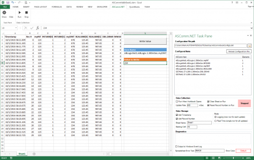
ASComm Excel Add-in is a simple to use, non-programmatic way to populate Excel 2007 - 2021 (version 16) spreadsheets with data from PLCs, instrumentation, and other process hardware. ASComm Excel Add-in uses built-in drivers for Siemens S7-200, S7-300, S7-400, S7-1200, and S7-1500 communications. No OPC, DDE, external drivers, or programming required. -

[Demo Software] - Excel Add-in for Siemens S7 Data Logging
Automated Solutions posted a topic in Download Comments
View File Excel Add-in for Siemens S7 Data Logging ASComm Excel Add-in is a simple to use, non-programmatic way to populate Excel 2007 - 2016 spreadsheets with data from PLCs, instrumentation, and other process hardware. ASComm Excel Add-in uses built-in drivers for Siemens S7-200, S7-300, S7-400, S7-1200, and S7-1500 communications. No OPC, DDE, external drivers, or programming required. Submitter Automated Solutions Submitted 03/01/16 Category Demo Software -
hey can someone help me i dont understand how to communicate a DATAMAN60 with a PLC s7-1200 through an RS-232 communication the problem is with programming the module that contains the RS-232 port i dont know if the DATAMAN60 send data automatically or i have some programming to do thank you
-
Hi: I know how to update the S7-1200 by this link: http://www.tecnoplc.com/actualizar-firmware-s7-1200-de-una-cpu-6es7-214-xxx-0xb0/ , but anyone knows about update the Firmware with other type of Memory Cards??? Is it available with 12MB or 4MB card??? Thank you a lot.
-
Dear colleagues and siemens experts, I''m new in siemens. As all I make my program for PLC, but I need help with PID autotunig (pretuning) I use : 1.CPU 1214C DC/DC/DC (6ES7214-1AG40-0XB0) 2. 6ES7214-1AG40-0XB02. 16IN/16 OUT DC/DC/DC (6ES7-223-1BL32-0XB0) 3. 2x 6ES7231-5PD32-0XB0 ( 4 channel RTD analog module - PT100) We use 7(seven) Pt100 points with 7(seven) heaters ... so I need 7 additional outputs..... [you can see example of wiring in attached pic 6es7231-5pd32-0xb0-modules.jpg] Maximum heating point is around 220 degrees. I make my configuration for PID_Compact : 1. Basic settings 1.1 Controller type : Temperature : °C Set mode to : Pretuning ( sometimes I make it Automatic mode) 1.2 Input_Per(analog) -----> Output_PWM 2.Process value setting: 2.1 Process value limits: Process value high limit : 220.0 °C 2.2 Process value limits: Default 3. Advance setting 3.1Process value monitor : Default 3.2 PWM limits Minimum ON time : 0.5 sec Minimum OFF time : 0.5 sec 3.3 Output value : Default 3.4 PID parameters : Default I start Commissioning with these steps : 1. Measurement : Sampling time 0.5 Start 2. Start PID_Compact 3.Tuning mode : Start When I try first time my setpoint was 90 degrees , second time I try with 120 degrees. After 4-5 hours it stop more in Progress bar it stop when I reach a little more then 50%, and I stop PID. For heaters it is not normal to process to be 4-5 hours, there have some wrong. Example with 120 degrees : During process I make : When Input_PER reach 120[1200] degrees I stop physical access to heaters. When Input_PER reach 100[1000] degrees I start physical access to heaters So 4-5 hours is soo long time for this type process. Time to reach 120 degrees from 100 degrees is around 2-3 min. Time to fall from 120 degrees to 100 degrees is around 4-5 min. Total time for one whole cycle around : 8min. Sometimes when I set setpoint to 140, 150 degrees it writes me that output set value is to high after I give Start Pretuning ? Even sometimes when try for 120 degrees .... As all I want to start PID pretuning (autotuning) with setpoint 140 - 150 degrees. Which are minimum requirement to start PID autotuning with PID_Compact ? Could you send me some very simple example and steps that I must make or only steps ? I attached files in dropbox with images and program example, because I can't attached nothing here. This form don't give me access to attached something. So link is here : Even program is there. Thanks in advance Best regards : Altan