Search the Community
Showing results for tags 'plc negative analog input output'.
Found 149 results
-
CP1L-L14DRD CP1W-AD041 I have my configuration words set to #80BB for both output words with the intention of having 0-10 input. With my input voltage at 5.25 I get 6300 the maximum range. I entered the bit wise in my calculator 1000000011011101 and it converts to 80DD. Tried both those options with the same result. Can anyone shed some light on what the problem is?
-
hello everyone , I am involved in the development of an industrial product. It has a 24 V On / OFF output signal which will be read by a PLC digital input. It could be Allen Bradley / Siemens . Can anyone tell me what would be the approximate values of the internal pull ups and pull downs? where can i find this? Thank you for all the help. Regards Sha
-

Frozen Analog Input on Compact Logix
Dan Truitt posted a topic in Allen Bradley / Rockwell Automation
This is a bizarre one... CompactLogix, 1769-IF8 with 1492-AIFM8-F-5 wiring system. My client has reported several instances where one of his flow rate displays is frozen at its maximum value. Each time, I have gone to the site, found that the value in the analog input tag is at full scale, and measured more than 20mA at the input - as much as 28mA! I measure it using a clamp-on meter and I measure it at the input module (1769-IF8) and the external, pre-wired terminal block (1492-AIFM8-F-5). I cycle power to the PLC. No change. I cycle power on the transmitting device. No change. I disconnect and reconnect the input (signal wire at the module or the terminal block) and everything goes back to normal. This has happened on multiple channels on multiple input modules and with two different types of transmitters. I didn't install this system, but it seems to have been done properly and it had been running fine for many years. These problems just started happening out of the blue. Has anyone out there had any similar experience? This is a new one for me after more than 25 years in the business. -
Buying all new industrial surplus and even some used.
TrojanSupply posted a topic in For Sale, Employment, Services or Wanted
Looking for any and all new industrial surplus and even some used on a case by case basis. Anyone have any questions feel free to email me at contact@trojansupply.com We also have some great deals on any items we have instock we compete on price as we are a small entity. Same day shipping available. -
Hello Everyone, This is first time i am using Omron's CX-Programmer. PLC- CP1L-EM40DT1-D I have 2 built in analog input of 0-10V on PLC Board. I want to know the default resolution, Data Type and Register address to detect analog Input for my further programming. Please Help me with these...
-
Is there any reason not to have input and output modules on the same rack as the processor and Ethernet cards? We have RIO’s and sometimes have networking outages, I want to move critical IO to Rack0 the same rack as the processor, is this bad practice? I've seen architecture for BMS that only have Ethernet cards and processors in Rack 0...
-
M241 - Modbus TCP - problema reading analog inputs (#300001)
horvatmiha posted a topic in Modicon / Telemecanique / Schneider Electric
Hello! I am new at programing PLCs. I am using TM241CE24R PLC with TM3AI4 analog input module. I can successfully read temperature from 4-20 mA sensor. I want to communicate with my PC (SCADA) via Modbus TCP. For testing purposes I am using CAS Modbus Scanner. I can read digital inputs, coils and holding registers successfully. Problem is that I can't read analog inputs (#300001 etc.). I have nothing defined in GVL list. Is this causing problem? I also don't have any Modbus TCP Slave device in Ethernet_1. But how can be all the other registers read successfully? Please take a look at screenshots below. Also check Error message from CAS Modbus Scanner. Where is problem? Please help. Thanks in advance! -
Hello, I used a Schneider Electric SR3B261B PLC to create a trivia machine (as I call it). Basically 20 buttons that let contestants ring in to trivia. There is a display that shows the number of the person who rang in. It works pretty well unless people press the buttons at exactly the same time. Then it shows 2 results at the same time. Usually resulting in a display of 18 when really it was 12 and 14 that rang in, for example. The PLC has options for: "Adjustment of the basic cycle time of the module." and "Type of Hardware Input Filtering." Which I assume would make the PLC operate faster and avoid two inputs triggering at the same time. If I change the setting and update the changes do not keep. I appear unable to change it past 20 x2 ms and slow (3ms). Is that a correct assumption that changing this would fix it? Why can I not change this? Is it because I have so many inputs (14 or so) and Outputs (16 or so)? or because my program uses nearly all 240 lines of ladder logic allowed? What can I do to fix this? Emerald
-
Is it possible to view the values / states of all inputs, outputs and workbits (e.g. 64.00 through 64.15 on Omron CQM1 PLC) on a single screen or control panel within CX-Programmer software? I'm trying to troubleshoot some ladder logic that I wrote and need to know the values of 5 or 6 inputs/outputs/workbits simultaneously. Having to scroll up and down through my ladder logic repeatedly does not work well with code that changes state every 5-10 seconds or so. Any help is welcome.
-
Hi, I'm using a CJ2M CPU 33, and also a CJ1m Ad-041-V1 Analog Input and DA-041 Analog Output card. I am using the Analog input to measure my current in my one heating application and Ihave that reading and scaled correctly, but now I want to use my Analog output to replace the Rheostat we have in the system. I'm having some issues setting the range and getting voltage to vary. I also am a little new to Analog Outputs and don't know what I'm doing wrong. I have attached my program here. Any help would be greatly appreciated. Analog Heat.cxp
-
Hi new to the forum, and first post, however, I have found an abundance of great information here, so I was hoping someone might able to help me with an issue. PLC is BRX BX-DME1-10ED13-D I am trying to read an analog output from a sensor that is capable of essentially outputting a mA signal proportional to where a printed line, or contrasting edge is at in its field of view. It is used for web guiding applications to make sure the web is tracking straight, so you can identify if the line or edge is moving to one direction or the other, and correct the web with an articulating web guide. I have attached the diagram for the sensor, but I cannot for the life of me figure out 2 things 1) The power supply to the sensor is listed as follows Supply current - From fife control +/- 12vdc 50ma (+)12vdc AND - 40ma (- )12vdc how do you provide both (+) and( -) 12VDC for the supply power to a sensor- 2 power supplies with the the opposite polarities grounded on each? 2) The outputs are listed as "Sum" and "Differential" so apparently there are two outputs, i dont know if anyone has come across these terms relative to sensors before, but I am trying to sort these out. According to the OEM Sensor Output Range -20 mA to +20 mA for line guiding -20 mA to +10 mA for edge Guiding I have attached the pin out diagram as well as the sensor spec sheet, but I am curious to see if anyone might have insight as to how I would get an analog input reading from this configuration? Thank you in advance for any help! 224615.pdf SE-26B Product Sheet.pdf
-
Some videos training PLC AB(Rockwell) RSLogix5000
hochiminh2019 posted a topic in For Sale, Employment, Services or Wanted
Here are some videos training PLC AB(Rockwell) RSLogix5000 I hope this helping someones! 1) Setup RSLink to connect PLC using a USB cable https://www.youtube.com/watch?v=mk-wgnwO4E82) How to set up hardware involve Input/Output, Analog, Device Net... PLC AB(Rockwell) RSLogix5000https://www.youtube.com/watch?v=pIUNPCEcNn03) How to use timer/counter/Compare PLC AB(Rockwell) RSLogix5000https://www.youtube.com/watch?v=7BDzAoFBJPMhttps://www.youtube.com/watch?v=EM3KO8JSYsMhttps://www.youtube.com/watch?v=yQtrIhTmwqA4) How to use Analog PLC AB(Rockwell) RSLogix5000https://www.youtube.com/watch?v=8raR0f7zr6M5) How to use RealTime-Clock PLC AB(RockWell) RSLogix5000https://www.youtube.com/watch?v=Lgg8hjs5jkY -
RealTimeClock, Analog, Install Hardware PLC AB RSlogix5000
hochiminh2019 posted a topic in Allen Bradley / Rockwell Automation
Some videos show how to use Real-time clock Analog Install Hardware Using timer Using counter -
Please let me know if it is allowed to sell PLC hardware on your forum. I accumulated lots of Omron hardware that I want to get rid off. Here is the list, I have several of each type, asking $12 each plus shipping. All in working condition. Base Unit C200HW-BI051 Base Unit C200HW-BC101 16 Point DC Input Module C200H-ID212 16 Point Digital Output Module 24VDC C200H-OD212 Power Supply Module C200-PA204
-
Hi, Anyone can help how to program a analog coming from a level transmitter? I have 8 analog inputs (2 unit of FX3U-4AD) to be read out into the plc program. how can this be possible. I'm new to mitsubishi analog. it is different from my experience(using siemens before). Hope someone can help. Thanks!!! Marky
-
Anyone have experience with the Peak to Peak hold function on Keyence IL-1000 amplifier? I have an IL-030 lase head running off it and I want to utilize the peak to peak hold function. I connected the red wire from a generic 24VDC, 1A, power supply to the IL-1000 Pink/Purple (timing input wire) and the black wire from the power supply to IL-1000 Blue (0V). I have a 24VDC, 5A, power supply connected to IL-1000 Brown (10-30V) and IL-1000 Blue (0V) to power the IL-1000. What I thought might work is to plug the 24VDC, 1A power supply in and out of an outlet to trigger the timing input for the P-P hold (similar to an on/off button). But it's not doing anything. I am not an electrical guy. Any tips here? Thanks,
-
Hello! I'm running into a problem with a malfunctioning OD212 output card on my PLC. I figure the problem has something to do with my wiring, because I've put 2 different cards in with the same results. The card is unable to switch any of the relays I have as outputs although the indicator lights on it are functioning as expected. The setup it is in is: A PA202 power supply, followed by a CJ1M CPU13 CPU, 2 ID211 input cards, and 3 OD212 output cards. The bad card is the second OD212. All of the other cards work fine, it's just this one that's been having problems. 8 of the terminals on the bad card are hooked up to relays that each draw 0.02A and two more are attached to relays that draw 0.05A. So in total that's 0.26A if all the outputs are on at the same time (which they never will be.) I saw someone was having a similar problem to me on the forum, which was solved by switching out the PA202 supply, but that didn't work in my case. I don't think the problem lies with the PLC or the card's placement in the rack because I switched the card's position with the one next to it (output card 2 switched with output card 3) and tested that card (output card 3 in output card 2's place) without hooking it up to the original wiring and it worked just fine. However, I was still getting the same issue with the bad card even though it was in a different position, leading me to believe that I fried it somehow. Some other quirks of the bad card are that its outputs do not turn on and off with the indicator lights like how the other OD212s do. Below is a link to a video that shows this. The bad card has already been switched with the one next to it in the video - so it's on the end, but it's original position was second to last. https://youtu.be/wTvvGCHFpsc ( you may want to watch it at half speed ) So what I'm wondering is: how am I frying these cards / Is the problem easy to fix or will I have to send them to Omron? Thanks in advance!
-
Hello, Is there something similar in CX-Programmer to the (N) bit in Siemens programming software? If so, what is it called please?
-
PLC-5 BTR setup screen for manalog input module
jrsiscool posted a topic in Allen Bradley / Rockwell Automation
HI I'm using PlC5/20 when I click on setup screen on the BTR block (to view the analog input configuration) i find the following message: No modules exist in the IOconfiguration for this R/G/M however the analog input signals is running properly....i just want enter the setup screen for configuration. I'm assuming that I need to enter I/O module in the I/O configuration? Can I do this without taking PLC to Program mode? -
-
[PLC Sample Code] - CP1L-EL/EM Option Board Configuration
MPOLITIS posted a topic in Download Comments
CP1L-EL/EM Option Board Configuration View File FB for Option Boards in CP1L-EL/EM -Configuration of the option board left-right -Scaling Selection -Analog Input and Analog Output Conf. -Tested in CP1L-EM30 Submitter MPOLITIS Submitted 07/22/19 Category PLC Sample Code -
Version 1.0.0
201 downloads
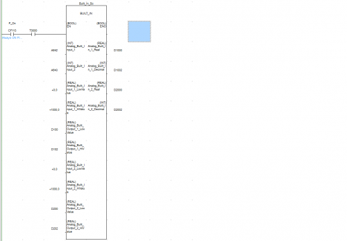
FB used for Built In Analog Inputs of CP1L-EL/EM With Scaling Set Up Included Demo_Built_In_v1.bak Demo_Built_In_v1.cxp Demo_Built_In_v1.opt -
View File CP1L-EL/EM Built In Inputs FB used for Built In Analog Inputs of CP1L-EL/EM With Scaling Set Up Included Demo_Built_In_v1.bak Demo_Built_In_v1.cxp Demo_Built_In_v1.opt Submitter MPOLITIS Submitted 07/22/19 Category PLC Sample Code
-
hi really i need the help from someone i dont have any idea about the step to a project i wish to someone support me and help step by step radouan_2020@hotmail.com
-
please can anyone tell me how to set A1S68DAV analog output module parameters , such as voltage output and resolution? or is the parameter can't be set at aLL (ie, fixed at -10V to 10V)?