Search the Community
Showing results for tags 'modbus rs485'.
Found 282 results
-
Hi, I have a problem with serial communication (no protocol) using rs485 module, the received data is error. I'm using CP1L CPU, CP1W-CIF11 module as transmitter, and USB to RS485 converter as receiver. When I check the received data on PC, it's incorrect (bit error?). I just send 2 bytes data, 0x61 ('a') and 0x62 ('b'). My configuration: DIP switch CPU 4 = off, DIP switch CIF11 1 to 6 = on,on,on,off,off,off, 2 wire RS485. (I also attached the program and settings) https://postimg.cc/gallery/pr293Jc Could you help me to solve this problem? Thanks Program and Settings: Result:
-
HI, I'm reading values from an SBC SAIA PLC ( PCD2.M5540 model). My problem is that some values are 32 bit, while modbus return 16 bit values, of course. Registers are consecutive, so I cannot read for example 9008 and 9009 since they store 2 different information.To make it clearer I attach the PLC watch window. As you can see R9009 is a 32 bit value, but I can't require R9009 and R9010 via modbus since in R9010 register there is a different information. AS well as in R9008. Speaking with SAIA technical support, they explain me that their PLC registers are natively 32 bit, so in order to read them I need a 32bit modbus client. I cannot find anything like this, neither I can use standard modbus, since the buffer I get back is a 16 bit for each register. So 16bit for R9008, 16bit for R9009, 16 bit for R9010. What I can do?Thanks
-

How can I access an UR5 robot through Studio 5000?
Lucas Antonelo posted a topic in Allen Bradley / Rockwell Automation
Hello, everyone! I am following this YouTube tutorial where it teaches you how to add a block of Modbus server within Studio 5000 for communication with plc ControlLogix. The video: https://youtu.be/qcF4m7rPjkw However, according to a comment from the author of the video himself in my comment I can make such a connection through a Modbus device. How do I do this within ur5 and how can i access UR5 inside Studio 5000? -
Hi, I'm new to the Mitsubishi world, so may be anyone help me in a quick! I need to test a my client with the Mitsubishi MODBUS tcp. To do this I would like to avoid use a real plc and use the Gx Simulator3 that come with the Gx Works3. The question is: the Gx Simulator3 is capable to simulate a MODBUS tcp module? To be more specific I tried this: - created a project in Gx Works3 with a FX5U CPU. - configured the FX5U built-in ethernet module with IP address of the hosting pc (also tried 127.0.0.1 with no success). - activated and configured the MODBUS muster to the built-in ethernet module. - wrote a trivial ladder program with a 1 input and 1 coil. I can download and run the project on the Gx Simulator3 but I cannot connect to tcp port 502 that I supposed opened by the MODBUS muster functionality of the build-in ethernet module. Do anyone know if the Gx Simulator is able to simulate modbus tcp functionality? Thanks in Advance Luciano.
-
Hi guys I need to test some code in an FX5U PLC, but I don't have the PLC here so I'm trying to simulate it in melsoft gx works 3, but how I can test the Modbus tcp/ip if I do not have an IP address for the plc someone has ever communicate both software, gx works 3 an som modbus master software ??
-
Hello everybody. I need a solution for Modbus-TCP server on the PLC. With the FX3U it would work with the FX3U-ENET module. The internal interface of the FX5U should actually be able to work with the library of the FX3U (FX3GModbusTCPServer_GW2_V100) or not? Because a socket connection is now possible. I would be happy about suggestions. Dave
-
Hello, I'm new to setting up my controllers and communication between devices. We wanted to see if using Modbus TCP/IP to communicate to a load bank was the right path for us. I was able to configure my Micrologix 1400 controller Channel 1 for Modbus and set the data files. I set up a read holding register 03 message, two write single register 06 messages and one write multiple registers 16. I was able to read the data from the load bank, but I was unable to send any write commands. I didn't get any errors in the messages. I was able to send write commands through my pc to the load bank and it responded properly. So I was thinking I must of missed something in my set up in the PLC. I'm attaching the PLC Program and the command set from the manufacturer. Any help would be greatly appreciated. BENCH_TEST.RSS ALx Series Input Command.pdf ALx Series PWR Command Page.pdf ALx Series Setpoint Command.pdf
-
Hi all; I have Delta DOP110 IS hmi and i have a modbus tcp device. I want to communicate hmi and device with modbus tcp/ip but i didnt understand device's register address. For example, input bytes 0,1 analogue control word, What is the register address? 40.000 or 40.001 can you help me ?
-
Hello, I am rather unexperienced with PLC's but have some experience. I Currently have 2 Lexium ILS1 motors which we want connected over RS485. I have read a couple of manuals. I have found which format they want to receive their data and what the pinout of their pre assmbled cable is (which hasn't been delivered yet). I am currently unsure about a couple of things. The wiring the formatting of my data i'm sending, and the program. The pictured below show my motor (which runs when i connect it to the PC and run it using the software provided so it is in working order) and the PLC with option port (which i used to transmit data to another PLC, so again i can't blame the hardware for being at fault here). However when i connect the cable and try to communicated I Don't see the LED light up. I followed Lexiums guide on which pins to use. But i figured for good form i might include these pictures to be certain hardware is correct. Finally here is my program. I followed Omrons quick start instructions. But: my send ready flags never become high and the way data has to be formatted for these lexiums seems very labour intensive. But this is how i understood it needed to be done. Am i doing something (or a lot) wrong here? I hope someone can help me out here! If any further information is needed i'll do my best to provide it. Kind regards.
-
Hello everyone, I have a problem, i want to read inverter holding register using modbus tcp. I am using QJ71MT91 and ABB580 FENA-21. QJ71MT91 successfully opened and no error was detected. I want to read the address to 101 and so on. in automatic communication parameter >> I have tried changing the target MODBUS Device Head from 0 to 102, and I got error code 7360. do I also have to use the auto refresh setting? I ask for guidance PLC Q03UDECPU : 192.168.3.181 PLC QJ71MT91 : 192.168.3.121 INVERTER : 192.168.3.11 i use gx works2 best regard chelz96
-

[Demo Software] - Modbus/TCP Client Driver Library for .NET 8.0, 7.0, 6.0, 5.0 & .NET Core 3.1 - ASComm IoT
Automated Solutions posted a topic in Download Comments
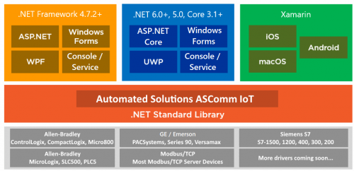
Modbus/TCP Client Driver for .NET 6, .NET 5 & .NET Core. - ASComm IoT View File ASComm IoT for .NET 6.0, .NET 5.0 & .NET Core developers. Class library for use in Visual Studio.NET to create HMI/SCADA apps that communicate with Modbus/TCP Server devices via Ethernet. Does not require OPC or 3rd party drivers Visual Studio.NET 2017, 2019 and 2022 compatible All .NET 6.0, .NET 5.0 & .NET Core targets are supported, including Web, Windows, console, and service apps. Runs on Windows, Linux & Android Extremely high performance - 5~10 mSec typical transaction time Supports Modbus functions 1, 2, 3, 4, 5, 6, 7, 11, 12, 15, 16, 17, 20, 21, and 24 Address mode support includes: Zero-based, One-based, Modicon 5-digit (1, 10001, 30001, 40001), Modicon 6-digit (1, 100001, 300001, 400001) Abstract base classes allow you to write generic code that works with all drivers Synchronous and asynchronous read/write methods Data change notifications Provides common user interface across all driver classes No limit on number of devices or data points Multi-threaded for high data throughput Includes extensive help system Example applications with VB and C# source code included. Easily connect office systems to factory floor. Runtime-free for qualified applications Submitter Automated Solutions Submitted 05/18/22 Category Demo Software -
Modbus/TCP Client Driver Library for .NET 8.0, 7.0, 6.0, 5.0 & .NET Core 3.1 - ASComm IoT
Automated Solutions posted a file in Demo Software
Version 1.4.1
34 downloads
ASComm IoT for .NET 8.0, 7.0, 6.0, 5.0 & .NET Core developers. Class library for use in Visual Studio.NET to create HMI/SCADA apps that communicate with Modbus/TCP Server devices via Ethernet. Does not require OPC or 3rd party drivers Visual Studio.NET 2017, 2019 and 2022 compatible All .NET 8.0, 7.0, 6.0, 5.0 & .NET Core 3.1+ targets are supported, including Web, Windows, console, and service apps. Runs on Windows, Linux & Android Extremely high performance - 5~10 mSec typical transaction time Supports Modbus functions 1, 2, 3, 4, 5, 6, 7, 11, 12, 15, 16, 17, 20, 21, and 24 Address mode support includes: Zero-based, One-based, Modicon 5-digit (1, 10001, 30001, 40001), Modicon 6-digit (1, 100001, 300001, 400001) Abstract base classes allow you to write generic code that works with all drivers Synchronous and asynchronous read/write methods Data change notifications Provides common user interface across all driver classes No limit on number of devices or data points Multi-threaded for high data throughput Includes extensive help system Example applications with VB and C# source code included. Easily connect office systems to factory floor. Runtime-free for qualified applications -
Hello, I have noticed that a frequent product here is the I-7561U. I'd like to know your reviews. What are you using it for?
-
how read data from modbus read_var function
saruans posted a topic in Modicon / Telemecanique / Schneider Electric
hello, Somebody have suggest how need read data from slave using modbus RTU. I am using M241 PLC and read_var function. The picture you can see my PLC program. The data of slave is placed 3394 address. Then I try to read, always "READ_VAR" function get "CommError" which number is 254 that means "The detected operation error contains protocol- specific code" and "OpenError" which number is 3 that means I don't know. How need read from slave data, which modbuss adress is 3394? -
Here is a post that we recently completed on the Automation Direct USB to RS485 Adapter. The USB-485M is a 2-wire USB to RS-485 serial communication adapter for RS485 use. It does not require an external power supply or complicated configuration. It has a Type A (plug) USB connector for the computer side and a universal female RJ45/RJ12 modular connector. This will accept RJ12 and RJ45 plugs. The USB-485M supports multiple baud rates and is USB V2.0 Compliant. Read the rest of the post... YouTube Video on the installation and communication to a Solo Process Temperature Controller via Modbus RTU. https://www.youtube.com/watch?v=aWE05ZNZNXw Let me know what you think, Garry www.accautomation.ca
-
Hi all, i am looking for a solution to connect 7 plc with a single scada. is it possible according to my topology diagram ? Kindly make me suggestion and if you have any information regarding the solution then share . Thanks in advance.
-
Hi there! I'm programming a CP1L-E CPU to control 3 3G3MX2 inverters via Modbus. It got some things right, like the INV002_Refresh_X31 block and its parameters. The thing is, I also want to read some parameters from the inverter using the INV206_ReadParameter block. My doubt is, do I need to be careful so both blocks don't execute at the same time and use the serial port at the same time? Is it better to use one INV206_ReadParameter block for each parameter I want to read? Thanks in advance!
-
I have this setup: FX3G CPU connected to GT2103 through RS422 (CH1). GT2103's ethernet port connected to LAN and set up as modbus TCP slave (CH2). I want to read/write PLC word devices using a modbus TCP client, from a PC. The HMI is acting as a gateway between PLC and PC. I used the Device Data Transfer function to send PLC's D register values to GT's internal GD registers. D0....D9 ==> GD0....GD9 After some tries, I get valid response from the modbus slave. Reading the holding registers 0....9 (40001....40009), I get only zero values. Those registers can be written back with different values, correctly. I'm sure I didn't understand correctly the modbus address mapping to GT's internal memory. Can anybody help me? Thank you.
-
Hello everyone I am working on modbus TCP protocols to communicate between SEW drive and Omron PLC CP1L-EM. I am following modbus TCP function block from Omron, But i have updated that block because of is not fit to SEW modbus communication. Currently, I am sending a control work to SEW but I am getting error on Modbus TCP from SEW drive, which is invalid data. So I am looking your help is you work with SEW drive before and communicate over modbus, then please let me know how to make a data string for read and write (SEW Drive function 23). I am using 3PD data structure. Thank you
-
Hello friends, I am an Omron PLC user, but have never used modbus before. I have to connect an Omron CP1L-m to Beckhoff bk7300 via modbus serial gateway. 2-wire RS-485 connection (CP1W-CIF11). I have seen an easy to use Modbus RTU master for CP1L CP1H CJ1 CJ2 CS1 but the examples are not for dual port CP1L-m. If I change the PLC model "CP1HCP1LModbusDualPort" to "CP1L-M", the compiler tells me a lot of warnings about variable types. Is Modbus RTU Master easy to use for CP1L CP1H CJ1 CJ2 CS1 compatible with CP1L-M dual port (port 2)? I have tried to use it but it didn't work, error 02, illegal function code. Somebody could help me? Thank you Enric
-
Hello everyone, may you all bless with the best. Can anyone please help me on connecting and programming In Modbus rtu INVT CHF-100A vfd with FX2n having rs485-bd moblue. I want to connect 11 vfd and one fx2n plc also
-
Hello everyone, may you all bless with the best. Can anyone please help me on connecting and programming In Modbus rtu INVT CHF-100A vfd with FX2n having rs485-bd module. I want to connect 11 vfd and one fx2n plc also .
-
Hello everyone, may you all bless with the best. Can anyone please help me on connecting and programming In Modbus rtu INVT CHF-100A vfd with FX2n having rs485-bd module. I want to connect 11 vfd and one fx2n plc also
-
Hey all, So I am looking for some assistance because I am not understanding how the tags on an HMI and within a PLC are linked. There are no 'physical' buttons, just what is on the HMI. It is controlling a chiller. Communicates over Modbus TCP/IP. The PLC is an IDEC. I have some-what worked out how other tags are working when they are words being passed back and forth, but this one has me stumped. I've attached a few screenshots for referral. It looks like the run and unload buttons for the chiller are a single bit/BOOL toggle (but the chiller running latches itself in the PLC when the chiller starts to run). The stop buttons appears to be a parent for the single bit/BOOLs and when it is pressed it resets them all both on the HMI side and within the PLC side.
-
Hi there, I have a controller NX1P2-1140DT. I want to control a VFD with modbus serial communication. Can someone help me start from scratch ?