Search the Community
Showing results for tags 'how to regain running process after power failure'.
Found 43 results
-

Daisy chaining power to Armorblocks
mephistopheles posted a topic in Allen Bradley / Rockwell Automation
Hey guys, I'm trying to power about 31 armor blocks in a daisy-chain. I'm running my power off a panel to a junction box and then drawing cables to Taps and dropping a cable to each Armorblock. I'm using 1732E-8x8M12DRs and 1732E-IB16M12Rs, which have 4-pin mini male ports for power. 1. Are there 4-pin mini cables (18AWG) Taps so I can power the entire system using 18AWG cables? 2. Is it safe to gave 22AWG micro cables and M12 taps and draw out a 4-pin mini cable drop to my armorblocks? 3. What in your opinion would be the best way to daisy chain power to these modules? Thanks! -
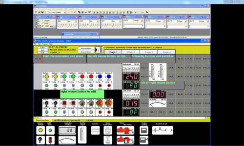
Good morning. My name is Mariusz Suder. I'd like to present the new process simulator PSPLC. PSPLC this universal process simulator can be used for building various technological models. PSPLC - is designed to work with PLCSIM v 5.x the part of Step7 and TIA Portal the Siemens™ PLC programming environment. There are plenty of typical devices and parts of industrial installations to choose which can be easily put or laid on the screen by simply selecting or dragging them. (...) PSPLC is the reliable process simulator. Useful for testing the PLC programs while they are executed or for learning programming the PLC controllers. Due to the intuitive user interface building models is quick and setting the devices easy. Colourful graphics, animations and high quality simultaneous sound. Language versions: English, Polski, Deutsch, Русский. Two units systems to choose: Metric and British Imperial. OS: Win XP, WIN 7 For further information please visit my internet site: http://www.sudermariusz.com.pl/psplc_the_plc_process_simulator.html http://www.sudermariusz.com.pl/plc_programming_examples.html Download PSPLC PSPLC can also be downloaded from: mrplc/download/siemens/demo
-
Version 1.1.0
179 downloads
PSPLC - the PLC process simulator, version 1.1, July 2017 Description: "PS PLC" - the PLC process simulator is designed to work with PLCSIM v 5.x the part of Step7 and TIA Portal the Siemens™ PLC programing environment. This universal process simulator is used for building various technological models. There are plenty of typical devices and parts of industrial installations to choose which can be easily put or laid on the screen by simply selecting or dragging them. (...) Language versions: English(full), Polski(pełna), Deutsch, Русский. There are also two units systems to choose: Metric and British Imperial. press.bmp -
View File psplc PSPLC - the PLC process simulator, version 1.1, July 2017 Description: "PS PLC" - the PLC process simulator is designed to work with PLCSIM v 5.x the part of Step7 and TIA Portal the Siemens™ PLC programing environment. This universal process simulator is used for building various technological models. There are plenty of typical devices and parts of industrial installations to choose which can be easily put or laid on the screen by simply selecting or dragging them. (...) Language versions: English(full), Polski(pełna), Deutsch, Русский. There are also two units systems to choose: Metric and British Imperial. press.bmp Submitter Mario980 Submitted 07/13/17 Category Demo Software
-
I am currently in the process of an efficiency project for a company looking to measure at what point their process starts to create particulate (in this case, smoke) so we can accurately defer the smoke into a combustion chamber to be burnt off. My question is, is it possible to use the Dywer SERIES PMT2 Particulate Transmitter for our measurements using a CJ2M-CPU33 Omron Controller and CX Programmer. http://www.dwyer-inst.com/PDF_files/PDS/DS_PMT2Rev.1.pdf If we can use this, I am wondering which cards I would have to get for communication to this transmitter? CUrrently I have analog in and out, (DA041 and AD081-V1), and digital in and out, (ID211 and OC201). Any information on getting this sensor set up is appreciated. I am not familiar with this type of process control. *****FYI If this is not the correct topic to post this, please move it to the correct one.*****
-
how to regain running process after power failure fx 3u plc
-
PAROCK1 for HMI/SCADA View File Now a software solution is available for your Modbus (MB) needs in Rockwell/Allen-Bradley Control Logix or Compact Logix (Clgx) family processors, instead of a traditional 3rd party hardware like Prosoft MVI-56, Molex SST-SR4-CLX-RLL etc. It is an Add-on instruction (AOI) for PLC/PAC firmware v16 or later, (other solutions are available for pre v16 systems). For hardware interface, use PLC’s channel 0 (serial) or TCP/IP Interface module(s) to have as many MB TCP/IP devices or serial devices. (Some limits apply based on system configurations, Comm. settings depending on HW used.) Connect any MB Client/Master or Server/Slave device(s) to your CLgx PLC, including flow computers, analyzers, VFDs, Power Monitors, Level gauges, Smart I/O, etc. All the MB public/native function codes are supported. 32-Bit integers/floats as single entity are supported with byte and word level swapping. A separate utility automates the data mapping to your PLC logic. Features -Serial Master (BASIC required Option); TCP; Slave; Redundancy; More than 5000 accumulative registers; MB CFC (Custom/Private Function Code) Support; Data mapping too – Between PAROCK1 & your PLC logic; Packaged with Rockwell; TCP/IP Interface Module; Volume Discounts; Annual Support Requirements -Rockwell/AB-CLgx processor with v16 or later. Contact PCI for earlier versions. -If using CPU’s Chan0, you cannot use Chan0 for any other user mode activity. You can use it for non-user mode activities -TCP/IP Interface Modules from Rockwell/AB supported, are: -1756-EN2xx ControlLogix® Ethernet/IP communication modules, firmware revision 5.007 or later -1756-EWEB ControlLogix Ethernet/IP web server module, firmware revision 4.006 or later -1768-EWEB CompactLogix Ethernet/IP web server module, firmware revision 1.002 or later -1769-L30ER, 1769-L30ERM, 1769-L30ER-NSE, 1769-L33ER, 1769-L33ERM, and 1769-L36ERM CompactLogix controllers, firmware revision 20.011 or later -1769-L24ER-QB1B, 1769-L24ER-QBFC1B, 1769-L27ERM-QBFC1B CompactLogix controllers, firmware revision 20.011 or later -1769-L16ER, 1769-L18ER, 1769-L18ERM CompactLogix controllers, firmware revision 20.011 or later Other Related Services/Items -Custom PLC Add-on instructions building -PLC upgrades, troubleshooting, applications -PC Windows, iOS5, Linux, Mobile devices Comm. Drivers -Custom development, Technology Transfer Services -Other Non-AB communication drivers for serial or TCP -Full control system integration, training, architecture design This driver can be conviniently used with Visual Studio in development of complete large scale complex HMI/SCADA Systems. It can be used to perform advanced reporting MES, analytics, IoT, Big data type apps. One example is available to download here For More Info Overview of Parijat Drivers: Click here Additional supporting Info about Parijat Drivers:Click here Complete Related Driver options: Click here Submitter Scadadoctor Submitted 03/10/16 Category Other PLC Demo Software
-
Hi, I'm using FWRIT to log data and want to know if it's possible to detect power failure to not write to the CF memcard? You can extend the power OFF up to 10ms or use the power off interrupt. Does anyone make experience with that?
-
I have restored a crashed IFIX to a new PC. The restore is ok and installed GE9 driver. With the GE9 power tools, we can observed that data transmits and recieve. The problem is that the screen scada is not updating i.e. no status/feedback, anything is happening. The LAN network TCP/IP was configured i.e. IP, subnet and gateway. Any remedies/advice is most welcome. Please provide a guide on the communication/configuration setup. Thanks
-
Power SCADA Expert 8.0 Need help. May I know how to start for this power scada and how to use Template Editor, Profile Editor, and the equipment editor?
-
ABB Power Generation Portal Couldn't Go Online
Eddie28 posted a topic in General Topics - The Lounge
Hi everyone, Currently i am having a PGP server fail to connect to the node as per the ICI status screenshot as per link below. https://www.dropbox.com/s/0qg435zkqzou9p3/Node%20Disconnected.bmp?dl=0 Appreciate anyone can assist me on this matter. I'm a new control engineer who just started working in a power plant and has limited exposure to the troubleshooting of this and i really hope that any of you can assist me. Thank you very much. -
I have an EP24DC module that will not supply power to the bus. Swapped the module out and still have the same issue. Any Idea's !
-
At work we have been having a slightly increasing number of instances where the Micrologix 1400 that is paired with a Panelview C400 resets values when we cycle the power. Originally we thought the solution was a bad battery in the ML1400. This was the case the first few times that it happened. However, we recently had one doing the same thing and when the program was loaded onto another PLC and HMI combo it had the same issue. So either the battery for both just happen to be bad, or there is something in the program that is forcing the values to automatically reset when the power is cycled. I cannot post the program on here but I can tell you that the tags that are being reset are only used in the PLC program once. There are six total that are being reset and they are the high and low range in an SCP function that is used to scale inputs. I will be testing the program myself in house on a bench setup, but I wanted to get this question out there as soon as possible in case it is not an obvious problem. Has anyone seen this before? Any suggestions? If I come up with an answer I will post it. Thanks.
-
In our SIMATIC OP7 console ram failure message is appering while power on, do anybody know about the problem and its remedy ?
-
I wonder if there is version of Ethernet Remote IO that can be used with 115VAC supply rather then 24VDC? This would save me a power supply which is really needed for this module only.
-
Downloading new program to 1746-BAS via Hyperterminal
ME90 posted a topic in Allen Bradley / Rockwell Automation
Hello all, I am trying to download a new program to a AB 1746-BAS SLC 500 BASIC board via RS-232 connection through a Windows 98 laptop running Hyperterminal. While the BASIC board is connected I verify connection by waiting for the board to print out its information in the Hyperterminal program and then enter "CLEAR", "NEW" and finally, "LIST" in Hyperterminal to wipe any program from the board and verify the board is clean respectively. Then I load the new program via a .TXT file using the "Send Text File" option within the Hyperterminal program. After the program has finished loading I than type "LIST" to verify it has copied over correctly. I than switch the SLC over to "Program Mode" via the key. After doing so I type "RAM" to select the program i just uploaded to the BASIC board and then type "PROG" in the Hyperterminal program. I than receive the "Programming Sequence Failure". If anyone has any advice as to what I am doing wrong it would be greatly appreciated. Below is a list of everything I have set and researched. Thank you in advance, James -Laptop: Windows 98, Hyperterminal -BASIC board (programming): JW1 pin: 1-2 3-4 JW2 pin: 1-2 3-4 JW3 pin: 1-3 2-4 JW4 pin: 5-6 3-4 -RS-232 9-pin connector: Pin 2 connected to Tx Pin 3 connected to RX Pin 5 connected to ground Pins (4/6) crossed DSR/DTR Pins (7/8) crossed RTS/CTS -Hypterminal: Direct Com1 bits per second: 1200 parity: none stop bits: 1 Flow control: Xon/Xoff Settings/properties: -> Emulation VT100 -> ASCII line/character delay: 30 milliseconds check box: Append line check box: Wrap lines... -Manuals: 1746-rm001 1746-pm001 -
Reading Kwh on Power Meter PM800 Series using Vijeo Citect v6.0
budimanc posted a topic in Modicon / Telemecanique / Schneider Electric
Dear All, I have a little problem in reading data from Power Meter to Vijeo Citect v6.0 I'm using Schneider PM810MG for Energy reading from Power Meter and for the SCADA I'm using Vijeo Citect v6.0. I can do some simple data reading like current, voltage and the others using variable tags from Vijeo Citect with Data type INT. But i dont know how to read the data for "Real Energy In" since the data range from 0 to 9,999,999,999,999,999. Waiting for all your help soon. Thx. Best Regards, Budiman Chandra -
Someone could give me an example of a batch programming or batch process? Because it does not know exactly how to program a batch... Thanks!