Search the Community
Showing results for tags 'hmi with modbus communication'.
Found 411 results
-
Dear Forum, I am working on a set of "drivers" for some VFDs and wondering about you guys experience with it. The system layout is as following: FX5UC RS-485: MODBUS-RTU RS-485, lets say with 1x Mitsubishi F840, could be other drives (one drive per FX5UC) Ethernetport: Connected to GT2510, using Freqrol driver Another setup is for some other reasons not possible. I want to have one PLC program for different connected VFDs, scheduled VFDs at the moment are: Mitsubishi F-840, ABB ACS880, Toshiba L.V. VFD, Toshiba T-300MVi. What I want to do: Read & Write status information - done. Read monitoring values - done. I want to setup some VFD parameters via the HMI. Send the parameter to the PLC and from the PLC to the VFD. The parameters are "basic VFD parameters", every VFD should have, such as: Torque boost, accel/decel time, min/max frequency, base voltage/frequency, etc. Of course these parameters are not simple Pr.0 to Pr. 125 but spread all over the place. I want to check for min. and max. limits inside the PLC before transmitting the data to the VFD. Knowing "basic parameters" will turn out quickly to "VFD specific parameters", I want to be prepared on the programming side. The APSRW for read/write parameters are called through the program and hand shakes with other APSRW calls. What would be a good approach do to the above? I rather invest more time into the PLC programming rather complicated HMI-Handling. Reading simple 125 words and the next 125 words, then writing 125word and again the next 125 words? Reading / writing individual parameters? Reading / writing 125 parameters at once? Any other approach for implementation? Best regards, MarkusR
-
Has anyone done a Mitsubishi FX5U PLC Modbus interfacing with an Omron NX1P2 PLC? Trying to find that since no manuals exist on the Mitsubishi site as well as Omron.
-
Hello everyone Does anybody knows how to estblish a communication between 2 Mitsubishi CPUS with modbus? THey are RCPU and FXCPU
-
Data is loaded on PLC omronCP1E and HMI NB7W-TW00B no commission to PLC serial cabel are new
-
Hi I need to get data from a modbus rtu device to Omron PLC NJ501. I am using SCU32 or SCU42 as serial gateway. I have tried using sendcmd function, but I am having problrm with the DstNetAdr Here's my setup Cpu NJ501 1400 ID262 OD263 AD041 V1 EIP21 SCU32 My sendcmd parameter DstNetAdr.NetNo:=USINT#0 DstNetAdr.NodeNo:=USINT#4 DstNetAdr.UnitNo:=BYTE#16#84 senddata array 02 03 00 6A 00 02 E4 24 Anyone has any idea on how to do it?
-
Hello, i have a curios problem in a modbus tcp reading from a client. The HC900's answer for the variable 20 (holding register 6375) is clear in the Hybrid Control Designer (the variabile is a simple counter of flow gas counter). The ammount of value is incremented every pulse from a digital input. But when i send the request from a client modbus, the value's variable is different (completely). For example the value is frozen from this morning, probably when the machine started up. The others value read directly from analog inputs are correct. Only this value elaborate from some blocks show this problem. I can't understand the cpu's logic for elaboration the exchange area memory modbus. Best regards, Ennio .
-
Hi, This is Kaviraj. I am using Q06udv cpu + 3 ethernet cards ( 1 eth card for kepware connect , other two cards for modbus tcp connecting 16 GOC43 devices through predefine protocol). I am getting the data to PLC but facing below issue. Problem-01 (major) in 2nd and 3rd card i am facing X19 (Initial normal completion signal) bit OFF after some time randomly like 1 or 2 hours later. Problem-02 Connection ports are closing regularly like 1.5 sec to 2sec after port open status. so i am managing by executing port open instruction instantly after 200ms of port close status. Need help, pls support.
-
I am currently trying to connect my OMRON NX1P2 1040DT1 (Using CIF-105) to my Unitronics V570 PLC, With my OMRON PLC as Master. It seems as if Unitonics Rs485 only wants a six-wire connection type but my OMRON PLC wants a 2-wire or 4-wire connection, Wondering if anyone has a solution to my problem and can assist me.
-
Hi, How can I communicate Codesys and Intouch. Can you help me.
-
HI, I'm reading values from an SBC SAIA PLC ( PCD2.M5540 model). My problem is that some values are 32 bit, while modbus return 16 bit values, of course. Registers are consecutive, so I cannot read for example 9008 and 9009 since they store 2 different information.To make it clearer I attach the PLC watch window. As you can see R9009 is a 32 bit value, but I can't require R9009 and R9010 via modbus since in R9010 register there is a different information. AS well as in R9008. Speaking with SAIA technical support, they explain me that their PLC registers are natively 32 bit, so in order to read them I need a 32bit modbus client. I cannot find anything like this, neither I can use standard modbus, since the buffer I get back is a 16 bit for each register. So 16bit for R9008, 16bit for R9009, 16 bit for R9010. What I can do?Thanks
-
Hi all, I am trying to modify the date and time of several PLCs from other PLC. Them are all CJ2M, and they are all in the same ethernet network (192.168.100.xx) and in the same FINS network (#1). I am doing it using the FINS command 07 02 ("CLOCK WRITE") with the CMND2 instruction. It is not working entirely: the clock time is being modified at the specified node; however, I do not get the FINS response (expected 07 02 00 00). If I modify the number of retries of the CMND2, the command is repeated all the specified retries though the clock was already written on the first try. The D+0 and D+1 (response channels) are always #0; nevertheless, the I+1 ("Communication Completion Code" channel) allways receives #205. Acording to the manuals, this code is for "Response Timeout". I have tested it with 10 retries and with 10.0 seconds of monitoring response time, but it is working in the same way: the clock is modified fast enough, but I am not getting the FINS Response and the I+0.00 bit is ON after 100 seconds... I have been also doing tests with the OMRON's Etherway Software, sending the same FINS command, and here I am getting the response properly. (???) I would say the FINS network was set-up correctly. All the PLC were set in network #1 with Cx-Integrator. In fact, they are currently sharing several channels using the SEND command on this network #1. I don't know what I am not doing right... Any idea? The ladder is attached as .cxp and as .png. Thanks a lot. Best regards. CLOCK_WRITE.cxp
-

How can I access an UR5 robot through Studio 5000?
Lucas Antonelo posted a topic in Allen Bradley / Rockwell Automation
Hello, everyone! I am following this YouTube tutorial where it teaches you how to add a block of Modbus server within Studio 5000 for communication with plc ControlLogix. The video: https://youtu.be/qcF4m7rPjkw However, according to a comment from the author of the video himself in my comment I can make such a connection through a Modbus device. How do I do this within ur5 and how can i access UR5 inside Studio 5000? -
Hi, I'm new to the Mitsubishi world, so may be anyone help me in a quick! I need to test a my client with the Mitsubishi MODBUS tcp. To do this I would like to avoid use a real plc and use the Gx Simulator3 that come with the Gx Works3. The question is: the Gx Simulator3 is capable to simulate a MODBUS tcp module? To be more specific I tried this: - created a project in Gx Works3 with a FX5U CPU. - configured the FX5U built-in ethernet module with IP address of the hosting pc (also tried 127.0.0.1 with no success). - activated and configured the MODBUS muster to the built-in ethernet module. - wrote a trivial ladder program with a 1 input and 1 coil. I can download and run the project on the Gx Simulator3 but I cannot connect to tcp port 502 that I supposed opened by the MODBUS muster functionality of the build-in ethernet module. Do anyone know if the Gx Simulator is able to simulate modbus tcp functionality? Thanks in Advance Luciano.
-
Hi guys I need to test some code in an FX5U PLC, but I don't have the PLC here so I'm trying to simulate it in melsoft gx works 3, but how I can test the Modbus tcp/ip if I do not have an IP address for the plc someone has ever communicate both software, gx works 3 an som modbus master software ??
-
Hello I have a problem whit PLC mitsubishi FX3U thernet communication, we have a module FX3u-ENET-ADP. and we have the error "**03 Special Parameter Error".
-
Dear All, Am new to Siemens plc. i have CPU 315-2DP. but when i try to communicate with pc through simatic Manager . i receive the Following Error. " Unable to establish a connection with module ." Sometimes it gives error as attachments. kindly help me out. Through control panel , i have selected the PG / PC interface to S7 Online with PC adapter Auto 1. Kindly help me out. you will be a life savoir. Regards, ZUbair
-
Hello everybody. I need a solution for Modbus-TCP server on the PLC. With the FX3U it would work with the FX3U-ENET module. The internal interface of the FX5U should actually be able to work with the library of the FX3U (FX3GModbusTCPServer_GW2_V100) or not? Because a socket connection is now possible. I would be happy about suggestions. Dave
-
I am trying to POST API to a meter in Maximo using a socket in a 5069-L320 controller. I am able to successfully create and open the socket. The write and read instructions get the DN bit but I do not see the meter updating in Maximo. I was able POST successfully using Postman, so I know I am sending the correct information. Do I need to be formatting the POST differently? I'm not getting errors so don't have a direction to go from here. (I will fix the obvious username and password vulnerability, one step at a time) Thanks
-
Hello, I'm new to setting up my controllers and communication between devices. We wanted to see if using Modbus TCP/IP to communicate to a load bank was the right path for us. I was able to configure my Micrologix 1400 controller Channel 1 for Modbus and set the data files. I set up a read holding register 03 message, two write single register 06 messages and one write multiple registers 16. I was able to read the data from the load bank, but I was unable to send any write commands. I didn't get any errors in the messages. I was able to send write commands through my pc to the load bank and it responded properly. So I was thinking I must of missed something in my set up in the PLC. I'm attaching the PLC Program and the command set from the manufacturer. Any help would be greatly appreciated. BENCH_TEST.RSS ALx Series Input Command.pdf ALx Series PWR Command Page.pdf ALx Series Setpoint Command.pdf
-
Hi all; I have Delta DOP110 IS hmi and i have a modbus tcp device. I want to communicate hmi and device with modbus tcp/ip but i didnt understand device's register address. For example, input bytes 0,1 analogue control word, What is the register address? 40.000 or 40.001 can you help me ?
-
Hello everyone, I have a problem, i want to read inverter holding register using modbus tcp. I am using QJ71MT91 and ABB580 FENA-21. QJ71MT91 successfully opened and no error was detected. I want to read the address to 101 and so on. in automatic communication parameter >> I have tried changing the target MODBUS Device Head from 0 to 102, and I got error code 7360. do I also have to use the auto refresh setting? I ask for guidance PLC Q03UDECPU : 192.168.3.181 PLC QJ71MT91 : 192.168.3.121 INVERTER : 192.168.3.11 i use gx works2 best regard chelz96
-

[Demo Software] - Modbus/TCP Client Driver Library for .NET 8.0, 7.0, 6.0, 5.0 & .NET Core 3.1 - ASComm IoT
Automated Solutions posted a topic in Download Comments
Modbus/TCP Client Driver for .NET 6, .NET 5 & .NET Core. - ASComm IoT View File ASComm IoT for .NET 6.0, .NET 5.0 & .NET Core developers. Class library for use in Visual Studio.NET to create HMI/SCADA apps that communicate with Modbus/TCP Server devices via Ethernet. Does not require OPC or 3rd party drivers Visual Studio.NET 2017, 2019 and 2022 compatible All .NET 6.0, .NET 5.0 & .NET Core targets are supported, including Web, Windows, console, and service apps. Runs on Windows, Linux & Android Extremely high performance - 5~10 mSec typical transaction time Supports Modbus functions 1, 2, 3, 4, 5, 6, 7, 11, 12, 15, 16, 17, 20, 21, and 24 Address mode support includes: Zero-based, One-based, Modicon 5-digit (1, 10001, 30001, 40001), Modicon 6-digit (1, 100001, 300001, 400001) Abstract base classes allow you to write generic code that works with all drivers Synchronous and asynchronous read/write methods Data change notifications Provides common user interface across all driver classes No limit on number of devices or data points Multi-threaded for high data throughput Includes extensive help system Example applications with VB and C# source code included. Easily connect office systems to factory floor. Runtime-free for qualified applications Submitter Automated Solutions Submitted 05/18/22 Category Demo Software -
Modbus/TCP Client Driver Library for .NET 8.0, 7.0, 6.0, 5.0 & .NET Core 3.1 - ASComm IoT
Automated Solutions posted a file in Demo Software
Version 1.4.1
34 downloads
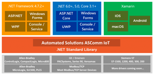
ASComm IoT for .NET 8.0, 7.0, 6.0, 5.0 & .NET Core developers. Class library for use in Visual Studio.NET to create HMI/SCADA apps that communicate with Modbus/TCP Server devices via Ethernet. Does not require OPC or 3rd party drivers Visual Studio.NET 2017, 2019 and 2022 compatible All .NET 8.0, 7.0, 6.0, 5.0 & .NET Core 3.1+ targets are supported, including Web, Windows, console, and service apps. Runs on Windows, Linux & Android Extremely high performance - 5~10 mSec typical transaction time Supports Modbus functions 1, 2, 3, 4, 5, 6, 7, 11, 12, 15, 16, 17, 20, 21, and 24 Address mode support includes: Zero-based, One-based, Modicon 5-digit (1, 10001, 30001, 40001), Modicon 6-digit (1, 100001, 300001, 400001) Abstract base classes allow you to write generic code that works with all drivers Synchronous and asynchronous read/write methods Data change notifications Provides common user interface across all driver classes No limit on number of devices or data points Multi-threaded for high data throughput Includes extensive help system Example applications with VB and C# source code included. Easily connect office systems to factory floor. Runtime-free for qualified applications -
how read data from modbus read_var function
saruans posted a topic in Modicon / Telemecanique / Schneider Electric
hello, Somebody have suggest how need read data from slave using modbus RTU. I am using M241 PLC and read_var function. The picture you can see my PLC program. The data of slave is placed 3394 address. Then I try to read, always "READ_VAR" function get "CommError" which number is 254 that means "The detected operation error contains protocol- specific code" and "OpenError" which number is 3 that means I don't know. How need read from slave data, which modbuss adress is 3394? -
Hello, I am using Hostlink protocol to read data from PLC units. for example @00RD22220001..., will return DM2222's value. But I want to know, if I could read multiple DM values at the same time. for example: DM2222, DM3000, DM4000, reading these DMs with one communication. Please note that these are not continuous DM areas. I know a sequence of DMs can be read by specifying starting address and count. Many thanks in advance. Ting