
Search the Community
Showing results for tags 'current input'.
Found 57 results
-
Hello, I used a Schneider Electric SR3B261B PLC to create a trivia machine (as I call it). Basically 20 buttons that let contestants ring in to trivia. There is a display that shows the number of the person who rang in. It works pretty well unless people press the buttons at exactly the same time. Then it shows 2 results at the same time. Usually resulting in a display of 18 when really it was 12 and 14 that rang in, for example. The PLC has options for: "Adjustment of the basic cycle time of the module." and "Type of Hardware Input Filtering." Which I assume would make the PLC operate faster and avoid two inputs triggering at the same time. If I change the setting and update the changes do not keep. I appear unable to change it past 20 x2 ms and slow (3ms). Is that a correct assumption that changing this would fix it? Why can I not change this? Is it because I have so many inputs (14 or so) and Outputs (16 or so)? or because my program uses nearly all 240 lines of ladder logic allowed? What can I do to fix this? Emerald
-
Is it possible to view the values / states of all inputs, outputs and workbits (e.g. 64.00 through 64.15 on Omron CQM1 PLC) on a single screen or control panel within CX-Programmer software? I'm trying to troubleshoot some ladder logic that I wrote and need to know the values of 5 or 6 inputs/outputs/workbits simultaneously. Having to scroll up and down through my ladder logic repeatedly does not work well with code that changes state every 5-10 seconds or so. Any help is welcome.
-
Please let me know if it is allowed to sell PLC hardware on your forum. I accumulated lots of Omron hardware that I want to get rid off. Here is the list, I have several of each type, asking $12 each plus shipping. All in working condition. Base Unit C200HW-BI051 Base Unit C200HW-BC101 16 Point DC Input Module C200H-ID212 16 Point Digital Output Module 24VDC C200H-OD212 Power Supply Module C200-PA204
-
Anyone have experience with the Peak to Peak hold function on Keyence IL-1000 amplifier? I have an IL-030 lase head running off it and I want to utilize the peak to peak hold function. I connected the red wire from a generic 24VDC, 1A, power supply to the IL-1000 Pink/Purple (timing input wire) and the black wire from the power supply to IL-1000 Blue (0V). I have a 24VDC, 5A, power supply connected to IL-1000 Brown (10-30V) and IL-1000 Blue (0V) to power the IL-1000. What I thought might work is to plug the 24VDC, 1A power supply in and out of an outlet to trigger the timing input for the P-P hold (similar to an on/off button). But it's not doing anything. I am not an electrical guy. Any tips here? Thanks,
-

PLC-5 BTR setup screen for manalog input module
jrsiscool posted a topic in Allen Bradley / Rockwell Automation
HI I'm using PlC5/20 when I click on setup screen on the BTR block (to view the analog input configuration) i find the following message: No modules exist in the IOconfiguration for this R/G/M however the analog input signals is running properly....i just want enter the setup screen for configuration. I'm assuming that I need to enter I/O module in the I/O configuration? Can I do this without taking PLC to Program mode? -
Are there any current recipe examples for omron na hmı?
CİHAN posted a topic in NJ Series / Sysmac Studio
Are there any current recipe examples for omron na hmı?Are there any current recipe examples for omron na hmı?Are there any current recipe examples for omron na hmı? -
Hi, I working on reading impulse from the input. I am using M8000 as a contact, on the coil [C235 K9999] and it is working fine on the lad, but the problem is I need to applicate sth like that in structure ladder but I dont know how. I found function on the image below but it is for FX3U. I know that 2-phase 2-count input use OUT_C(for example EN True| CCoil CC251| CValue K0) and then DMOV(for example EN True| s CN251| d D100), so is there any method to read impulses from the input? .Thanks in advance. PS I have Mitsubishi FX3G series.
-
I am using QJ71C24N to communicate with my devices, ASCII mode. I can send my output to the device by using non-protocol method ( G.output). However, when I using G.input to try to receive the feedback from my device. The signal seen not stable to receive by my PLC. Sometime can get the full signal sometime can't and sometime I get some messy signal. Is there any setting I need to set to get the stable feedback from my device? Please anyone can help me to solve this problem?
-
I need some help with G.input and g.output commands. I have a Q04UDEHCPU and my slots are as follow: slot 0 - QJ61BT11N cclink slot 1 - QJ61BT11N cclink slot 2 - QJ71C24N-R4 2-channel RS4222/RS485 I need to have 2 separate RS485 stings going to different devices. I cannot find the way of setting up the g.output command. G.Output "Un" (s1) (s2) (d) "Un" says it is the start I/O signal of the module, but I am not sure what that means. What there be a different "Un" number for each channel?
-
Hi, I am using Omron CP1E NA 20DTD with built-in ANALOG inputs and output. I know how to deal with digital inputs. But I have no idea about analogue input wiring and programming. I tried connecting gefran LVDT PY2 directly to an analogue input of plc. But the indicator light did not turn on. Do I need to use any signal conditioner or converter? The output of lvdt is 0 to 25volts. I HAVE ATTACHED THE DATASHEET OF LVDT. DTS_PY2_06-2016_ENG.pdf
-
I have project where I need to measure motor current but I do not need to control the speed of the motor since it would always be running at full speed. Do I still need to use VFD to get feedback or is there cheaper way to measure the current?
-
Excess Inventory Sale Item (Quantity limited)
ICPDAS-USA posted a topic in For Sale, Employment, Services or Wanted
Have 10 POE Analog Input Modules available on clearance 10/20-channel Voltage Input, Current Input, & Analog Input Module with High Voltage Protection PoE Module, communicable over Modbus TCP and Modbus UDP Model Number PET-7017-10 Regular price $459.00/EA Clearance price $344.25/EA only good on clearance quantity only. http://www.icpdas-usa.com/pet_7017_10.html -
Negative volt 0 to -10v analog output plc
Dipen posted a topic in For Sale, Employment, Services or Wanted
Hi I am searching for plc having negative analog input and output. i.e. 0 to -10v analog i/p and Analog o/p. Can any one help me in finding plc which has this feature . Thank You -
Lexium 32A hardware limit status
genn posted a topic in Modicon / Telemecanique / Schneider Electric
Hi, Iam new to schneider electric PLC drive programming and also to canOpen communication. I have an LMC058 PLC and there are three Lexium 32A drives connected via canOpen which inturn controls three servomotors. My question is how to find/ read hardware limit status of the axis in which limit is connected to a digital input pin of the drive. Even though the axis is properly working by configuring the digital input pins we are unable to get the digital input status of the drive. In the drive manual its given that the digital input status can be read from canOpen address 3008:F(hex) we dont know how to read the status during run time in the program . Can any one advise me how to read that address. I tried SDO_read function but its giving me error(canOpen network id Unknown). Thanks in advance. -
I'm working on a project that reads an RF - TAG via RS232. It uses the G.INPUT command. I need some help to see if I understand clearly how it works. Now it reads a maximum of 16 digits but in the future i want to pass it to 32 bits. The command line is |G.INPUT U5 D6500 D6800 M7922| If I understood correctly I load in D6500 either 1 or 2 to tell it which channel to read from. It stores the 16 digits in words starting from D6800 and goes on till D6815 if I am correct. My questions are: - did I understand correctly how to use the command and is there anything else i need to take care of while using it? - do I need to do additional settings to it in order to read 32 digits or does it automatically read (if the RF reader is compatible with 32 digits)? Thank you, Andrei
-
Hi! I have my 1756 IF8 wired in high speed differential mode but i can't configure the RTS smaller than 11 ms. What I understand it should be possible to set as low as 5 ms if module filter setting is 1000 Hz. Is there anything else that i have to do?
-
Hi to everyone, I use PowerFlex 520 drive on profibus (with adapter 25-COMM-P) for first time. I managed to start/stop/reference drive using Logic Command/Status I/O but didn't manage to get output current using datalinks mechanism. I configured DP master (Mitsubishi Q PLC, QJ71PB92V) as shown in the attached picture. The main problem is that trying to modify C161-C164 (Opt Data In 1-4) parameters drive does not accept the entered values and it turns back to value "0". First, I disabled I/O connection with the controller Disconnecting the drive from the network. On the other hand, drives allow me to change parameters C165-C168 (Opt Data Out 1-4) but these are out paramenetrs (from the controller's point of view). Is there any guy that managed to get the output current in any way on profibus network? Thanks a lot for your help in advance! I post this message in Allen Bradley Forum, too.
-
Hi to everyone, I use PowerFlex 520 drive on profibus (with adapter 25-COMM-P) for first time. I managed to start/stop/reference drive using Logic Command/Status I/O but didn't manage to get output current using datalinks mechanism. I configured DP master (Mitsubishi Q PLC, QJ71PB92V) as shown in the attached picture. The main problem is that trying to modify C161-C164 (Opt Data In 1-4) parameters drive does not accept the entered values and it turns back to value "0". First, I disabled I/O connection with the controller Disconnecting the drive from the network. On the other hand, drives allow me to change parameters C165-C168 (Opt Data Out 1-4) but these are out paramenetrs (from the controller's point of view). Is there any guy that managed to get the output current in any way on profibus network? Thanks a lot for your help in advance!
-
Good day, I'm new to this forum and to mitsubishi PLC but was hoping for some assistance with a programming issue. I have been through the hardware and programming manuals without luck for this issue. Hardware: FX3G-60mt FX3G-2AD-BE Settings: Structured ladder/FBD Current input mode on: M8260 (first board, first input) What I need to do is to record the peak value over a cylinder stroke period. The hardware manual explains how to average the value using averaging time, however I basically need to peak hold and send that to a D register for go no-go compare. Process as follows: Contact closed, monitor D8260, contact open, move peak value from D8260 during monitor duration to D205. Thanks in advance for any assistance. -Swervomotor
-

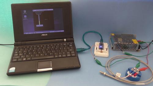
Temperature measurement using Arduino Nano, RTD PT100 temperature sensor and 4-20 mA transmitter
Absolutelyautomation posted a file in Other PLC Demo Software
Version 1.0.0
130 downloads
Temperature measurement usind Arduino Nano, RTD PT100 sensor, 4-20 mA current loop transmiter, and a python app for visualization -
[Other PLC Demo Software] - Temperature measurement using Arduino Nano, RTD PT100 temperature sensor and 4-20 mA transmitter
Absolutelyautomation posted a topic in Download Comments
View File Temperature measurement using Arduino Nano, RTD PT100 temperature sensor and 4-20 mA transmitter Temperature measurement usind Arduino Nano, RTD PT100 sensor, 4-20 mA current loop transmiter, and a python app for visualization Submitter Absolutelyautomation Submitted 04/01/16 Category Other PLC Demo Software -
Greetings, I've been having some issues with a vacuum pump breaker tripping... I think I've figured out the problem and resolved it but I noticed that several of the other motors have current monitoring on the HMI but the person who set this up is no longer with us. I'm wondering what I need besides an analog input for my control logix processor (which I have) to setup this project. I'm not sure if the other motors are just monitoring one leg of the 3 phases or if they are somehow showing total current? any ideas and recommendations would be greatly appreciated. thanks,
-
How to take single bit form input WORD by Structured Text? Can i write somethink like: inVar[i]
-
FT view studio security code for the numeric input enable button
Jiggadoo posted a topic in Allen Bradley / Rockwell Automation
Hello! I am programming with FT view studio version 8. In the program, when I make numeric display, I can not input values for this tag I am using in the display. Then I decided to make 'invisible button' for enabling the input for this tag which is shown in the numeric display. This is okey for me, only if there is other ways to do this please tell me. Now when I have created this numeric display with input enabling -'group', I have a problem, how can I use security levels for this group, so that only logging in values can be set? I have found that there is security code selection for this in the screen displays, but not for the buttons.

