Search the Community
Showing results for tags 'cant see point address in point editor'.
Found 52 results
-

PowerFlex755 is running always with the same Frequency
MatthisJosewski posted a topic in Allen Bradley / Rockwell Automation
Hello guys, I am new to this forum and have some problems with my PowerFlex755 EENET frequency inverter. I want to do a point to point positioning task but my problem before I can have a look at the point to point positioning is, that the inverter is always running with 5Hz as soon as I give the start command. Even if I write 0.0 to the reference the output frequency is about 5 Hz. When I change my reference speed to 10.0Hz the output frequency is 12.X (see attached screenshots). . I thought that maybe a min frequency of 5Hz was set somehow, but I couldn't find a parameter and that wouldn't explain why I have 12.X Hz as the output frequency with a setpoint of 10Hz. And an other question, have someone experience with positining tasks with a PowerFlex755 and Point to Point positioning? I think in the first step it is not working because of the problem I described above, but maybe someone have a programming example or could tell me where I can find some information about how to use the Point to Point positioning? Thank you for advice! Matthis Josewski -
Hi all, I am working on a safety PLC conversion project, for which I need to identify the input word address configured on a PSS AI IP card. The manual from the official website shows the address configuration via a DOS tool. I do have PSS SW PG WIN 4.9, but the project file has been created with PSS WinPro 2.3. Within this software there is only the option to configure how the input channel behaves, not which input word is used (see attached screen grab). Anyone with a distant memory if the addresses can be set with PSS WinPro?
-
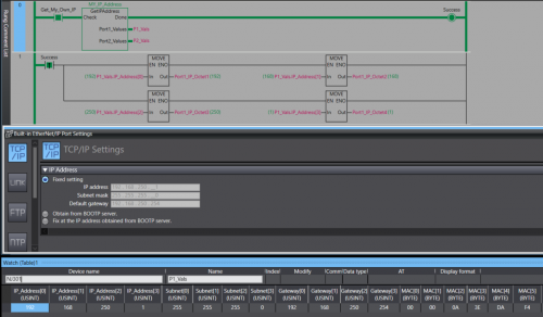
View File NJ/NX Get IP Address A Library containing a function Block that can be run on any Omron NJ or NX PLC. The Function Block will retrieve the host PLC's IP address, Subnet Mask, Gateway, and MAC Address. The Port Details are presented through 2 structures , 1 per-port. In the event the PLC only has one port the structure for Port 2 will be blank. Submitter photovoltaic Submitted 12/12/22 Category PLC Sample Code
-
Version 1.0.0
75 downloads
A Library containing a function Block that can be run on any Omron NJ or NX PLC. The Function Block will retrieve the host PLC's IP address, Subnet Mask, Gateway, and MAC Address. The Port Details are displayed through 2 structures , 1 per-port. In the event you only have 1 Ethernet port then the structure for the 2nd port will contain all 0s. Data Format: IP Address - USINT[4] Subnet - USINT[4] Gateway - USINT[4] MAC - BYTE[6] (hex value) Access the retrieved details by the typical parent-child tag structure. ex. Port_1_Detals.IP_Address[0] will get the first octet of Port 1's IP. Tested on: NX1P2, NX102, NX502, NX7, and NJ301 IMPORTANT: This Function Block should not be run immediately after startup. Allow the PLC a few seconds to establish a connection with the Ethernet network. -
Is there an efficient tool to manage and validate CX-Programmer addressing. Requirements: - Highlight Duplicate Address allocation - Compact/Defrag address range to avoid wasting memory space. Note: - Any FINS addressing will have to be reconfigured - This approach assumes symbol use rather than direct addressing in the logic.
-
It will de nice to have an option for getting a cross-reference report for the AT address used on programs , as is now its easy to make mistakes double setting the same AT address on a program , specially this days that supplies of NA screens are not always availiable and using memory address is necessary for NB screens and SCADA communication and is difficult to keep track of the used address on a program , some times in global or in internals, right now its easy to make a mistake and use the same address twice , and this wont be detected on the compiling
-

Zebra Industrial Printer and Allen bradley L18ER printing via Ethernet IP
AniAutomationIndia posted a topic in Allen Bradley / Rockwell Automation
Mail me for Help if anyone is stuck during coding and settings. -
Hi I'm trying to set up Modbus RTU communication between FX3U PLC and a weigh module. I would use the ADPRW command using 0X03 to read the 16 bit Holding Register but in the weigh module the Data Address/Holding Register of the value I want to get is 400047 - 400048. How to translate the value in 16 bit? Thanks, Fabio
-

CompactLogix Point I/O Module Limits
ElectronGuru posted a topic in Allen Bradley / Rockwell Automation
Hey guys, I did a quick search here and didn't come up with anything, so hoping I'm not asking something that has already been answered. I'm looking at automating an existing plant which currently has zero controls, so starting from scratch. The process isn't complicated but the equipment is a bit spread out over a two story facility. We're thinking about using a CompactLogix 1769-L32, physically located as central as possible, with ten four-slot 1734 Point I/O blocks. My concern is that many Allen Bradley controllers limit the number of I/O modules you can add to the project. Like some 1756 controllers are limited to 30 local and remote I/O modules, CompactLogix controllers may be limited to 16 local and who knows how many remotes, etc. I can't find anything that spells it out explicitly in the Design Considerations Manual. The CompactLogix 5370 User Manual only says it supports, "a limited number of Point I/O modules that can be used as local modules". Nothing about networked modules. The CompactLogix Selection Guide clearly defines the number of network nodes, but nothing about the number of modules. Does anyone have any direct experience with this much Point I/O in a CompactLogix environment? I'm thinking that we're in an age of counting nodes, rather than modules but don't want to order the hardware without being 100% sure. -
Communicating between plc's with different IP's
plcaholic posted a topic in Allen Bradley / Rockwell Automation
I am trying to get produced and consumed tags set up between 2 1756 racks with different ip's. The 1st rack has an ip address 172.28.6.3. The 2nd rack has an ip address of 10.81.105.8. Would this be as simple as adding an EN2T card to one of the racks and setting the ip of one onto the same network? Or is there a better way to do this? -
Hi guys, I've just completed pre-commissioning on a Mitsubishi project which uses CCLink. My remit was to get the CCLink network up and running which I eventually did but not without issues. Basically, my problem was to do with the number of bits and registers consumed by a station. I read in a manual that each station consumes 32 bits and 4 registers for read and 32 bits and 4 registers for write. On my network I had 3 ST1H-BT modules occupying 2 stations each and 3 non Mitsubishi devices occupying 4 stations apiece. My RWr address starts at W300 and RWw at W500. Like I said everything matched up and I/O checks completed successfully. My question is, and I've trawled through the manuals looking for an answer, how is the number of points calculate? For example my non-Mitsubishi devices they occupy 4 stations, Expanded Cyclic Setting is Octuple and the number of points is 896. How is the 896 calculated? Thanks in advance
-
Dear all schneider Experts, anyone having "Vijeo designer screen editor"Software for XBT012110 megelis HMI. Please give a download link, I got very stuck to get this software #Advanced Thanking you......
-
Hi everyone My system consists of 2 main stations with 2 CPU Q06UDEH and connected together by QJ71GP21S-SX module but I don't know how to link the address between these 2 CPU together? so can anyone help me? Thanks so much
-
We have an iQ-r R08cpu that will not display some labels or addresses. The PLC and the machine it controls run as expected. However, when we read from the PLC, some of the labels and addresses are not shown. Although it runs as expected, we are hesitant to make any changes or write to the PLC. There is a screenshot attached. Any advice or solutions for this?
-
Hi folks, I'm trying to communicate with an old CompactLogix L35E via Ethernet. I have already establish communication via DF1 Serial port and was able to go online but I Do not know the IP address to communicate via Ethernet. Can someone please tell me how I could determine the IP Address or create a new one ? This Controller was remove from a working machine. Any help will be highly appreciated. Thanks, Anthony.
-
hallo all, I want to ask if I click "read PLC Data" the "points" will appear, I use the QY18A output module that uses 8 points but there is no choice, the smallest is only 16 points. so I can't put 148 in the "start XY" column ... will it affect the I / O address in the program?
-
Hello All, I will first state that I am very new to the world of PLC's. I do the control drawings where I work. I'm trying to figure out the 1734 Point IO, specifically the 1734-IA4. The manual states "Module power is supplied from the internal power bus". Does this mean I do not need to run ANY power wires to the modules? The installation manual shows points 4,5,6 and 7 as "L1" wires?? The system I am designing, from left to right has the following: 1794-PS13, 1734-AENT, 1734-FPD, Followed by Qty. 11 1734-IA4's. I'm bringing 120VAC and 24VDC to the 1794-PS13. From the 120VAC terminals, I run wires to the FPD. From the 24VDC terminals, I run wires to the 1734-AENT. On the first 1734-IA4, I would think I should bring any power there, because its already back plane fed...….correct? Or DO I run power wires there? Thanks in advance
-
Hello all, I am a beginner with PLCs programming. I have an issue on GX Developer programming software from Melsoft trying to program my Mitsubishi Q-series PLC. CPU is Q03UDCPU. When the program is written and I try to upload it to the PLC, with the write to PLC window, I check -Program -- MAIN and -Prameter -- PLC/Network/Remote, click EXECUTE and a message appears : "Device point that is set in parameter is not match the device point in PLC". I can't fix it. In Parameter - PLC Parameter - Q parameter setting (window) - I/O assignment tab : I have (see image). Whe I use CHECK button it says there is no error. The X41 input device is plugged on slot 1/00. I am making this folowing the instructions a PDF I found on the Mitsubishi electric's wesite : Q-series basic course (for GX Developer). Thanks for the help, A. S.
-
Logix 500 math instruction with Decimal Point
jimmy689 posted a topic in Allen Bradley / Rockwell Automation
Hi my problem may have a simple solution but i cant work it out. I need to use the Divide function but it wont let me use a decimal point in either Source A or Source B. Is there a way to use a decimal point in Logix 500 Math instructions? Im using an AB Micrologix 1400 PLC. Can you only use math instructions with whole numbers? is there a way around this? Thanks James -
Allen Bradley - Point IO - Power Distribution
monkey77 posted a topic in Allen Bradley / Rockwell Automation
I am definitely a newbie in the world of PLC's. So I hope this doesn't sound like a dumb question. I do the electrical design for PLC's and have only done this for a few short months. I am currently working with a Point IO PLC. This is the first one I've seen. Because of the qty. of input and output modules, we had to add 1734-FPD and 1734-EPAC to boost the power. Easy enough, I get that. I bring power to the 1734-AENTR.....then, do I hard wire to the next module, or are the next adjoining input/outs connected view the internal power bus? Same question goes for the 1734-FPD and 1734-EPAC. I understand to bring power to those devices, but do I hard wire to the first module or is it automatically connected via internal power bus? I have done my research before I posted on this site. I think some of the installation manuals for these devices are conflicting., I think that's why I'm so confused. Thoughts? Does anyone know of a good trusted manual for such a question. Thanks in advance -
IP/ Subnets and communication between subnets
Joseph 0028 posted a topic in Computer Help and Networking
Lets say i have a PLC, with a name PLC1 with IP/Subnet of 10.125.34.243/255.255.255.0 I have to communicate this PLC1 with 2 other PLC's, PLC2 and PLC3 PLC2 with IP/Subnet of 10.125.34.10/255.255.0.0 PLC3 with IP/Subnet of 10.125.46.10/255.255.0.0 I imagine that, all these three are in different subnets, and so there should be no communication at all, but when i tested it, PLC1 to talking to/from PLC2 and not PLC3. anyone know the answer to this ? How does it talk to PLC2 with different subnet, but not PLC3 which is in different subnet as well. -

Modbus address register exchange between Melsec-Q series PLC and ME96SSHA-MB Power meter
RV3.0 posted a topic in Mitsubishi
Please assist me with the following; regarding the ME96SSHA-MB Power meter data transition with Melsec-Q series PLC; We acquire to read various values on dedicated Modbus storage address registers at the simultaneous into a Melsec-Q series PLC via Modbus (TCP or RTU) for calculation purposes. Naturally, since the reading of these variables are to provide accurate instantaneous results, it is a requirement that these values are to be read at one scan. However, as can be seen below, there is a gap in address register range – of which, if all of these are scanned simultaneously, yields an exception error when read. This error is only avoided by scanning these data sets separately – which is not ideal for our application – since accuracy in calculations is imperative. -
Modbus address register exchange between Melsec-Q series PLC and ME96SSHA-MB Power meter
RV3.0 posted a topic in Mitsubishi
Please assist me with the following; regarding the ME96SSHA-MB Power meter data transition with Melsec-Q series PLC; We acquire to read various values on dedicated Modbus storage address registers at the simultaneous into a Melsec-Q series PLC via Modbus (TCP or RTU) for calculation purposes. Naturally, since the reading of these variables are to provide accurate instantaneous results, it is a requirement that these values are to be read at one scan. However, as can be seen below, there is a gap in address register range – of which, if all of these are scanned simultaneously, yields an exception error when read. This error is only avoided by scanning these data sets separately – which is not ideal for our application – since accuracy in calculations is imperative.