Search the Community
Showing results for tags 'analog programming'.
Found 175 results
-

Modicon Send 'CTRL' Keystroke
MusicalComa posted a topic in Modicon / Telemecanique / Schneider Electric
I have a Modicon NOM0200 unit connected to an access switch to send commands to various rs-232 devices. The Access switch requires a "disconnect string" to end communication with a particular port. The disconnect string is "CRTL+D", how can I send a "CRTL" keystroke from the NOM0200 unit? I know for carriage return it is "$R" is their a similar combination I can enter for "CTRL"? -
Hi, Anyone can help how to program a analog coming from a level transmitter? I have 8 analog inputs (2 unit of FX3U-4AD) to be read out into the plc program. how can this be possible. I'm new to mitsubishi analog. it is different from my experience(using siemens before). Hope someone can help. Thanks!!! Marky
-
I am trying to program an analogue output on a Siemens S7-1500 unit from a 4-20ma sourced analogue input scaled over 0-250 degrees. The analogue input will have an adjustable setting in the software for when the alarm status should occur and at this point I want the analogue alarm output to start to process at 4ma, at 5 degrees above the initial set point I want the analogue output value to be 20ma I have no idea how to do this so any help from people is greatly appreciated and advice on which analogue output card to use would be helpful.
-
PLC-5 BTR setup screen for manalog input module
jrsiscool posted a topic in Allen Bradley / Rockwell Automation
HI I'm using PlC5/20 when I click on setup screen on the BTR block (to view the analog input configuration) i find the following message: No modules exist in the IOconfiguration for this R/G/M however the analog input signals is running properly....i just want enter the setup screen for configuration. I'm assuming that I need to enter I/O module in the I/O configuration? Can I do this without taking PLC to Program mode? -
-
[PLC Sample Code] - CP1L-EL/EM Option Board Configuration
MPOLITIS posted a topic in Download Comments
CP1L-EL/EM Option Board Configuration View File FB for Option Boards in CP1L-EL/EM -Configuration of the option board left-right -Scaling Selection -Analog Input and Analog Output Conf. -Tested in CP1L-EM30 Submitter MPOLITIS Submitted 07/22/19 Category PLC Sample Code -
Version 1.0.0
201 downloads
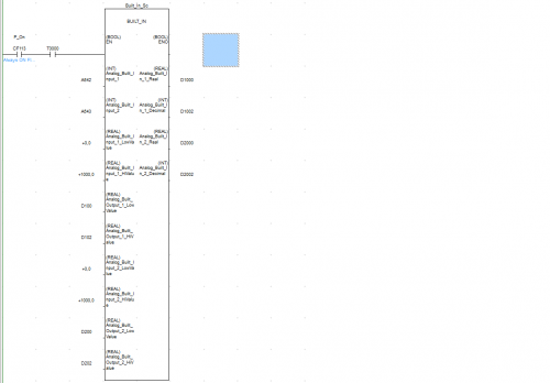
FB used for Built In Analog Inputs of CP1L-EL/EM With Scaling Set Up Included Demo_Built_In_v1.bak Demo_Built_In_v1.cxp Demo_Built_In_v1.opt -
View File CP1L-EL/EM Built In Inputs FB used for Built In Analog Inputs of CP1L-EL/EM With Scaling Set Up Included Demo_Built_In_v1.bak Demo_Built_In_v1.cxp Demo_Built_In_v1.opt Submitter MPOLITIS Submitted 07/22/19 Category PLC Sample Code
-
hi really i need the help from someone i dont have any idea about the step to a project i wish to someone support me and help step by step radouan_2020@hotmail.com
-
Hi guys. I have a new SRM50-HAV0-K01 sick encoder for my ELAU servo motor (model: ELAU sm 070-60-010-P0-45-M1-B0), and need to program it according to an old one (which seemingly is broken) via hiperface. device: PGT-11-S LAN software: SOPAS 2018.3 build 4.1.1.324 (Vm version 1.8.0_73) I tried to find any certain way for programming of sick encoders on the net using the mentioned device and software, but cant. all is only about datasheet or how to use teh software without an specific instruction. I am not even sure of that the old one is broken, except that in the analysis mode of the SOPAS (entering via hiperface) I can see the the sin-cosin graph out of its limitation line. The thing is I have bought a special tool which has not any specific instruction and SICK group does not reply any exact instruction for my issue. Here is my questions: How can I program the new encoder just according the old one? And how can I assure that the new one programmed just as the old one? and what is the definite sign of a broken encoder? anyone experienced?
-
please can anyone tell me how to set A1S68DAV analog output module parameters , such as voltage output and resolution? or is the parameter can't be set at aLL (ie, fixed at -10V to 10V)?
-
I have a control that I want to use a Direct logic 05 plc in. It is a really simple program but it is going into a plant that has a main control panel that runs the plant. I dont know the brand of the plc in the main control. They want to be able to send me a command from their plc to the direct logic to turn on my unit. I suppose that would mean a simple set instruction to my plc. I also have a couple alarm conditions that I want to send them. For example if water pressure is to low I would put my unit in the alarm mode and send them a low water signal. If the chemical is low likewise, I dont have a clue how to do this in my program. Can anyone give me some examples in direct logic plc program for making this happen??? Thank you Thank you Thank you. MikeC
-
Hi. We are struggling a bit with the analog IO on the EIC202 coupler. Have tried tag sets, and gotten the digital IO to work without problems, but not the analog. Any tips here? We are using 2x NX102 with 1x ID4442, 1x OD4256, and 2x EIC202 with 1x ID4442, 1x OD4256, 1x AD2603, 1x DA2603 on each, for a redundancy-system. Software is Sysmac Studio. EIP connection.
-
Hello, My apologies in advance if this is in the wrong place. I am working on a press that is using a 1746-INT4 to look at the position of the ram. The press is using an LDT as the sensor reading back to the INT4. It obviously works. The press runs everyday. I'm wondering if there would be a reason to use this instead of just a voltage or current analog card? Thank you in advance for the replies.
-
Hullo neighbors, We've got a LOGO! 0BA8 configured to use I8 as an analog input, and the goal is to read the current operating speed of an ABB ACS310 VFD. (we want our PLC to be able to react to any changes in speed from the VFD) Problem is, nobody can figure out how to hook up the analog output from the VFD to the analog input on the PLC. Have tried going from AO -> I8 and have also tried adding a connection from the LOGO! input neutral back to the GND... nothing works. Attached is the terminal diagram for both devices with our poor attempts labeled. Any insights?
-
Small and newly started Controls Company available to provide service in the following areas: Controls Design Panel Building PLC and HMI programming Commissioning Services 15+ years in controls and automation ranging from automotive to material handling. Experienced with Rockwell and OMRON Can ship panels to anywhere in the world from Canada Will design and or build your panels to your specs and according to CEC and NEC regulations. Can commission your machines on site. www.ashtoncontrols.ca
-
I am new to Automation Direct software and how the programs are written. Can anyone explain how they handle the analog outputs? My processor does not support the IBox that makes life easier, so I am having to do it the old hard way. I understand most of the logic of how its done for sending data to one channel but I don't understand how the channel selecting works. Can someone give me a programming example or explain how that works? I am looking at the online manual that Automation Direct provides for you for the analog module but I am having a difficult time trying to wrap my brain around how they do their analog stuff ><
-
I am new for gx devloper,I want 4 to 20 ma value to scale with 0 to 5000 and out put with PID. Plz help me.
-
Hello - I've recently started my adventure into PLC programming and I've found this site to be very helpful. I took on a project that requires control of a cylinder - the short and skinny is that the cylinder will have to provide position feedback and stroke to various set lengths determined by position of a selector switch. So - If position 1 is selected, the cylinder will stroke 20"inches. If Position 2 is selected, cylinder will stroke to 25"inches - so on and so on. My questions is how to best go about this process. I may be having a brain-block and not viewing this clearly, but something is not clicking for me and wanted some advice. Planned on using Allen-Bradley's Micro850 PLC (had one on the shelf, and CCW software is free so why not). Thanks
-
ML1400: Manipulate output through modbus/tcp
MikosMotta posted a topic in Allen Bradley / Rockwell Automation
Hello I have a scenario that's been bugging me for some time now. The scenario consists of a Micrologix 1400 that I need to control it's output from modbus/tcp. In detail what I really need is to be able to manipulate the O0:0 through modbus/tcp. The PLC would be the master and I would be the slave that triggers the connection to the master. I'm using a Modbus-Client on my PC and that should be the slave. Any idea as to how I can manage that? Currently I can send data to the master but everything is "stored" on B10 and I have no idea how I could write directly on O0. Thanks a bunch guys. PS: I'm borderline noob. -
I am trying to setup a MAD42 analog card up in a cpu33 omron controller. I need input 1&2 setup for 0 to 10 volt and can't get it to work. Any help is appreciated.
-
I'm looking for the SWPIC-3 PROSYS programming software from the C PLC English version programming system. I am also looking for BRKAOL5-1 Centronics / online converter Online operation through the PC parallel interface. Any help would be appreciated.
-
I am new to PlC programming . Plz can anyone guide me for ladder programming for FX5U -4LC Temperature controller with autotune parameters . Plus i want to use a PT-100 for the same . Plz help me out.
-

Enable Analog Channel in RSLogix 500 // First Scan Bit, COP function?
James275 posted a topic in Allen Bradley / Rockwell Automation
Hello all. I have been working with an SLC 5/04 system, which houses various Digital and Analog INs and OUTs, up to Slot 29. I am currently mainly working with Slot 25, an Analog Input: 1746-NI16I. This is a system which has already been set up and has been running for the best part of 8-10 years. This particular card has had some spare inputs, one of which I am trying to connect to. In the Advanced Configuration, only a few Channels are actually "Enabled", and each channel is pretty much slightly different from another in terms of Input Type, Filter Frequency and Data Format. I am trying to set up Input 14, which is Channel 15, to "Enable" it, 4-20mA Input Type, Filter Frequency of 6 Hz and Data Format of either Raw/Proportional or Engineering Units. Now, after I have made my choices, I click apply, and then OK. I am then confronted by a pop-up which states: "Configuration Rung and Data Integer Data File Number: 25 Integer Data Element: 100 Rung to be inserted: XIC S2:1/15 COP #N25:100 #O0:25.0 24 At Program File Number: 4 82" I have the options of OK or Cancel. If I click OK, I now have LAD 4, Rung 82 Highlighted. This First Scan Bit and COP function were already here, but does that mean I have now altered what is being written to "#O:25.0"? I now Download the Changes. However, after all this, I am not getting any Analog input reading coming in from the Live PLC. What is this COP function? What does it do? How do I properly set up this Analog Card? Thanks for your time, -Jame -
Hello. Can anyone tell me if there is a function for this in gxworks2? I want to even a jumpy analog signal. I am aware there is a MEAN-function, but that needs me to feed an array of buffered analog values to it. Which I am not familiar with how to do. Cheers