

jimmy.wong
MrPLC Member-
Content count
9 -
Joined
-
Last visited
Posts posted by jimmy.wong
-
-
I-DB is the safety Program auto-generate DB which is not allow programmer to access.
Based on this error message is insufficient to find out the problem, could you provide more information?
-
You may consider to use Array in your case.
First, arrange your alarm into few categories. Assume now I have 4 categories and they have different number of alarm,
category 1: 30;
category 2: 45;
category 3: 50;
category 4: 25;Second, create 4 array of bits based on number of alarm bit in that category:
category 1: ARRAY [0..29] OF BOOL;
category 2: ARRAY [0..44] OF BOOL;
category 3: ARRAY [0..49] OF BOOL;
category 4: ARRAY [0..24] OF BOOL;Third, you can map the alarm bit into the dedicated alarm bit by using Ladder diagram or structure text or other language. Assume the array is under DB101.
DB101.DBX 0.0 := Emergncy_Stop_Alarm; (*Structure Text example*)I'm using DB address (DB101.DBX 0.0) here but if you assign a name in your program, you can use the name to call.
Lastly, wish my idea could help you.
-
On 11/28/2016 at 0:32 AM, bagged2drag said:I am hoping someone can help me.
I have a siemens system in our facility that was built by a 3rd party. It arrived in less than stellar fashion, and doesn't work as it should. After 10 months of being here and not getting any resolve, I am going after it myself to tackle what should be relatively mundane issues to fix. That said, I have an AB background, and have worked with Automation direct, eaton, and fanuc controllers. I am new to siemens. I have made my way around the ladder pretty well, but I am having some issues with the HMI. Specifically, the vendor programmed in manual controls for our system, but they do not all work. I checked the HMI tags; they appear to match the plc tags as I expect, but when I press the HMI buttons on the screen, in online mode, I cannot see the tags become energized in the ladder. The corresponding manual controls subsequently do not work. The manual controls that do work, I can see the bits energize when I press the HMI buttons.
Is there anything specifically I should be looking at that I am overlooking possibly? Typically, the HMI is an easy part of a project, but I am a bit dumbfounded by my inability to figure out something so seemingly simple.
Thanks,
KK
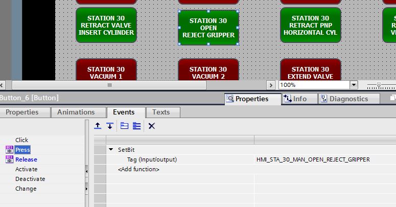
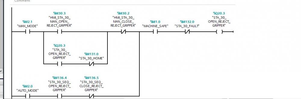

1) I checked the HMI tags; they appear to match the plc tags as I expect, but when I press the HMI buttons on the screen, in online mode, I cannot see the tags become energized in the ladder.
How you confirm the HMI tags is match to the PLC Tags. Is it by DB address? You need to make sure the HMI is link to the correct PLC addrrss.
2) The corresponding manual controls subsequently do not work. The manual controls that do work, I can see the bits energize when I press the HMI buttons.
What means corresponding manual control subsequently do not work and the manual control that do work? This mean manual control work or not working?
-
Try to delete SDB1002 and download again?
-
On 1/5/2018 at 0:29 AM, Allen82686 said:So the l1 is going to be the input from the power supply, correct? since the supply is a 120vac in/24vdc out, i would run the 24v to the input of the cpu since it is the dc/dc/dc model. Then the #4 is going to run the power to my PB's or toggles, and then back to my inputs so when the switch is pressed, it will activate that input. am i on the right track? Then the outputs, im not sure what exactly i need to do. power to the 1 &6, which leaves 6 lights all wired to a neutral?
Hi Allen,
Yes, your CPU is taking 24VDC as incoming power supply. Jairus's photo is another CPU modal.
-
I guess you could use "Read_Var" and "Write_Var" to read and write.
-
Hi everyone, currently I have a problem need to receive data from a Omron PLC to another Omron PLC. I would like to receive data from source EIP21 to destination ETN21. The steps I have done is:
1) MOV #0020 D16180 (*Read 32 Words From Source*)
2) MOV #0000 D16181 (*Use Local Network*)
3) MOV #8400 D16182 (*Source PLC IP address is 192.168.5.132*)
4) MOV #0003 D16183 (*Resend Time Set To 3s*)
5) MOV #0000 D16184 (*Response Monitor Time Set To 0s*)
6) RECV 400 D16130 D16180 (*First Source Word: D400, First Destination Word: D16130, First Control Word: D16180 *)
Can help me check the is there any problem and any more steps I miss?
Thank you.

Which software for what PLC?
in Siemens
Posted
Simatic Manager can support redundancy CPU but TIA portal so far not support.