

Akahige
MrPLC Member-
Content count
107 -
Joined
-
Last visited
Posts posted by Akahige
-
-
For the FX5 ADP modules the addressing, like the FX3U, are dependent on the location of the ADP device. for the FX5U-4AD-ADP module addressing the first expansion the Special Relays associated are SM/SD 6300-SM/SD 6459, second expansion SM/SD 6660-SM/SD 6819, 3rd expansion SM/SD 7020-SM/SD 7149, 4th expansion SM/SD 7380-SM/SD 7539.
I assume it is the same for the FX5U-DA-ADP module as well (did not look for in that same manual).
Look for the corresponding manuals on http://us.mitsubishielectric.com/FA/EN. They are free PDF downloads.
I found the above information in the MELSEC iQ-F FX5 User's Manual (Analog Control) manual number JY997D60501B
Hope this helps.
-
3 hours ago, Steris34 said:I've been reading on different forums and have seen people complain about the GX Works3 software a fair bit. Are there any specific function sets or features that are difficult to use? Is the software really buggy and unpredictable? Are the instruction sets poorly defined or documented? I would be very grateful if you could help me out and let me know what about the programming environment is frustrating. Thanks!
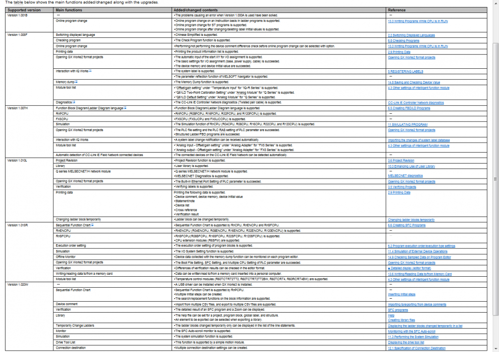
GX Works 3 is still in new release and though true that functionality does not match Works2, they are continually updating the software to include and or fix complained items. With the latest release (V1.020 I believe) Simulation is available.
One thing about Mitsubishi, their support is free and if you register your software on their website they provide a years worth of updates for free.
-
FYI: usually the causes of a 2501 CAN'T EXE PGM is that when multiple programs are created in a project. The scan sequence for the programs needs to be set, the PLC will not assume first program created (MAIN) will be the first program scanned. In parameters under the Program tab is where each program can be placed on an execution list.
-
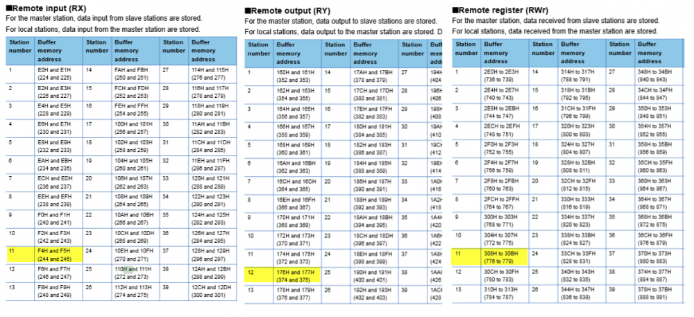
According to your logic. The reference buffer memory addresses is for station 25 not 11 (H0B). So you are loading empty registers. According to the manual for (assuming you are using a Q series CC Link Module) The station 11 remote inputs are located in BM address F4H, remote outputs are 174H and remote registers RWw are 308H.
Oops. Highlighted the wrong station for remote outputs. But you get the idea.
 1 person likes this
 -
Does if fault out or just not show the pens in the trend screen?
I sometimes find that the data register referenced is not scaled properly on my graphs. In the properties sheet/Data tab, along the bottom, adjust the upper and lower limits for the reference registers.
-
Teria que o número da peça ser FX0N - 32MR - ES?Axon - 32MR - ES não é um número válido parte MitsubishiPara o primeiro, software GX Developer é o que você está procurando. -
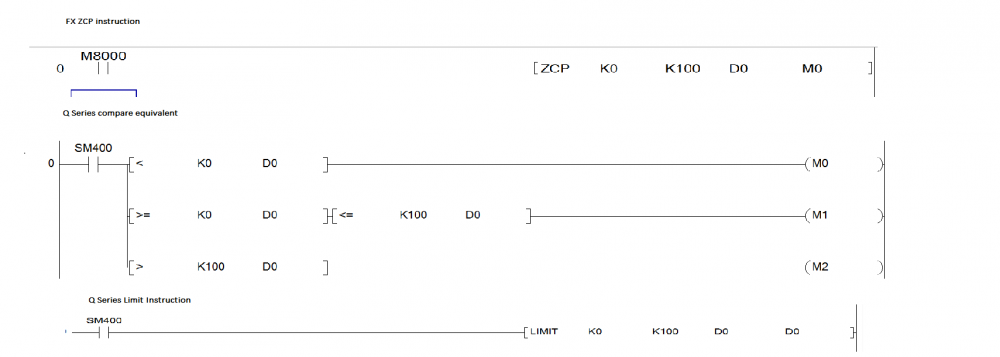
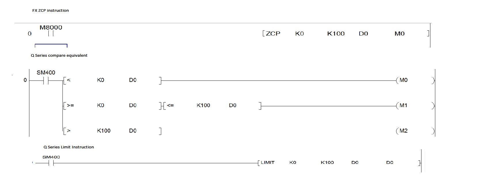
There is no exact equivalent to the ZCP instruction (as well as the CMP instruction) in the FX program.
The best equivalent is using comparison statements. Or even a LIMIT instruction. But the LIMIT is ... er ... limited compared to the ZCP instruction. It only allows a data register to be clipped between the lower and upper values.
Hope this helps.
 1 person likes this
 -
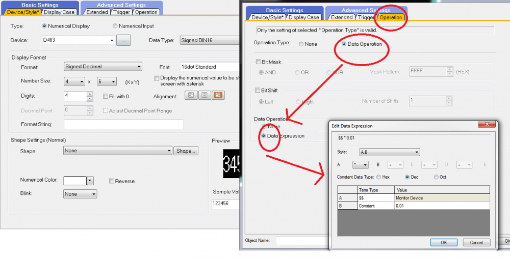
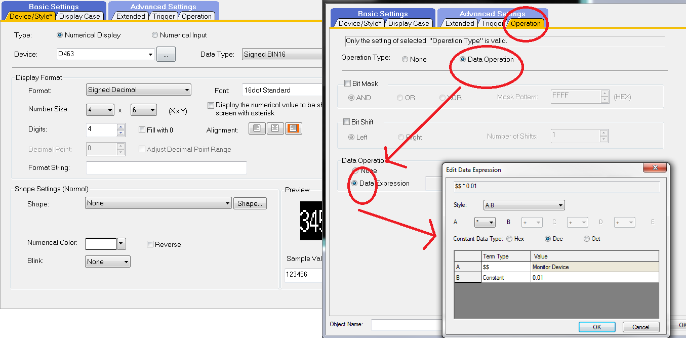
When you place a numeric display on your base screen select the Device/Style tab and place the device reference. I used your example above. Select the Operation tab click on the Data Operation radio button and then the Data Expression button. In the Edit Data Expression window put in the equation $$*0.01. This will take the value in D463 and scale it to the hundredths.
4000 = 40
Hope this is what you were asking for.
 1 person likes this
 -
No annual renewal fees for licensing. Free technical support. Enough said.
-
There is also using the DATERD/DATEWR (Q/L series PLCs) or the TRD/TRW (FX and older series PLC) instructions.
For example to read the clock data use an instruction like [DATERRD D100] then D100 will contain the year, D101 the month D102 the day, D103 the hour, D104 minutes, D105 seconds and D106 the day of the week. Now you can use these data registers for logic concerning certain times of the day.
You should use an oscillating timer for a command input, like SM412, to update the data registers every second.
-
I suspect that SD registers are non retentive which is probably why the value was written to the data register D270. A latch range can be set for these devices to retain its value on power cycle.
My reasoning is because I use SM414 and 415, modifiable timers when moving a value to their corresponding SD registers. When I cycle power they revert to the default K30.
-
Try this link:
http://www.mitsubishielectric.co.jp/fa/download/search.do?mode=manual&kisyu=/got&lang=2
1 person likes this -
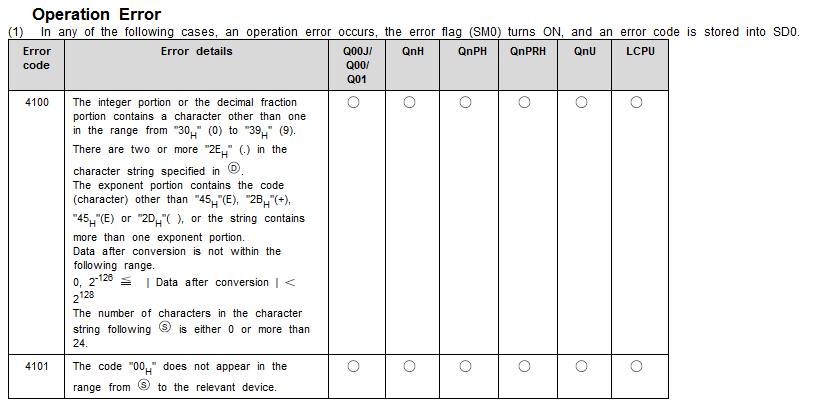
What is the error that occurs? Check the PLC diagnostics while it is in error for the error code. The following is a list of errors available in the manual for the EVAL instruction.
It looks like you are executing an EVAL instruction for each consecutive Data register, I might guess your error is a 4101 if anything.
-
Go to the Contact tab on the following site. They should be able to provide a local vendor to supply you with GX Works2 software.
-
On 1/14/2016 at 7:36 AM, panic mode said:exactly....
here is same thing but written a bit differently

I like it! Save on the steps and concise and to the point. I am going to have to "borrow" this on my next go around.
-
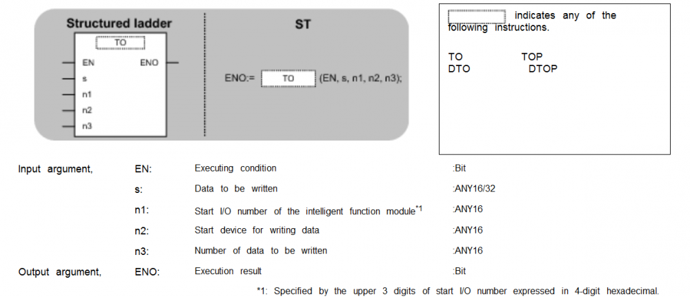
When using the To instruction with function block programming the sequence is ENO:= TO [EN, s n1, n2, n3]; Where n1 is the start I/O of the special function module(location of one of the FX2N-2DA) and n2 is the buffer memory location for that SFM. U\G addressing replaces these two addresses where U=n1 and G=n2.. Same argument goes for FROM instructions.
-
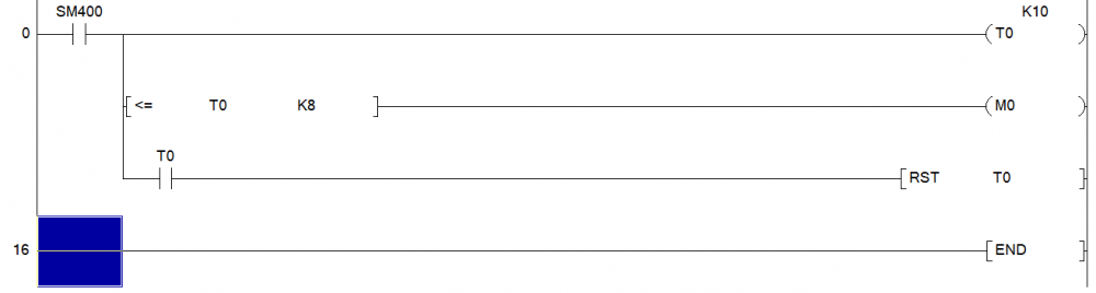
this should do it.
-
Ron,
The GT10s have a USB-A (big box end like the old printer port USBs) port on the back face for programming while the RS-232 or RS-422 interface plugs on the side would be for connecting to your FX1n.
As for programming software any revision of GT Works will work. The latest available is GT Designer v1.145.
Hope this helps

-
On 12/30/2015 at 3:41 PM, Alan Skinner said:As for display, I have an iPad on the wall that is hooked to my network. Would really love to have a graphical display with that data on it.
Any leads on that idea?
Hi Alan,
I would be interested in hearing if and how you got the iPad interface and graphics going on your project. Please keep us informed.
-
Hello Changjeff
The communication to a Q PLC depends on whether you are using GX Developer or GX Works 2. Open the corresponding Transfer Setup window.
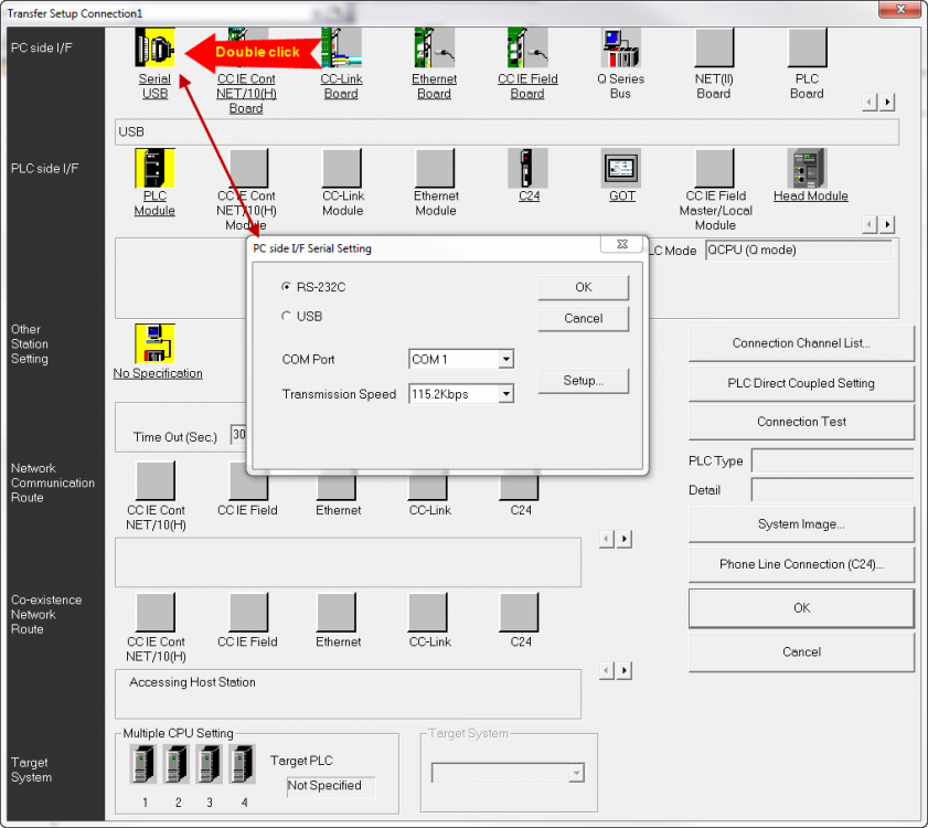
To select the PC side Serial interface double click the image for Serial/USB. A popup window will give you the option of USB or RS-232C, click the RS-232C radio button then select your Com port and baud rate from there (typically the default settings work with most PLCs). The Setup button also gives you the options for Parity, Data and Stop bits.
Once done click the OK button.
Other required selections are PLC Module for the PLC side I/F and No Specification for the Other Station Setting
When all three items are selected (in yellow), click on the Connection test button to the right to verify that you are communicating with the PLC with the serial connection. A popup window will indicate success or failure to communicate.
IMPORTANT: Once done, Press the OK button when done, not the red X on the upper right corner. The red X will close transfer setup without your selections made.
I hope this helps, I have attached a picture of the proper transfer setup (GX Works 2) for serial connections.
Regards.
-
Assuming that you have set the IP address on the FX3GE to Channel 1 (giving you a default IP address of 192.168.1.250) and then in the GOT1455 programming software you've set the communications port as Ethernet. Opening the Controller Settings for the GOT you add an FX Ethernet channel where the default settings come up as IP Address 192.168.1.254 with a port of 5551. You will need to change the Port No. to 5556 (the only other option). Port 5551 is reserved for mount on ENET module to the right (called Special Function Modules). Port 5556 is reserved for left side mounted ENET Modules (called Adapter Modules). Since the FX3GE places an Ethernet port on the left this port address is now configured as one of the two allowed expansion ports. 9 times out of 10 this is the common issue when setting up Ethernet comms with the new FX CPUs. Hope this helps. -
FX2
in Mitsubishi
Naseer look at the wiring diagram provided in the following forum thread: Home PLCs and Supporting Devices Mitsubishi sc 09 wiring diagram The wiring diagram is useful for creating your own but I would recommend purchasing it. If your PC does not have a serial port consider a USB to serial adapter for this cable. -
Gambit is correct. First check your PC's device manager to see if you have the yellow error triangle next to a USB communications device. If so all you will need to do is update the driver for it. Right click on the erred device and select Update Drivers. Browse for the driver loaded onto your PC with the programming software in the following folder: C:\Program Files (x86)\MELSOFT\Easysocket\USBDrivers You will also need to setup GOT Transparent Mode through the transfer setup once the drivers are up to date. Depending whether you are using GX Developer or GX Works2, the transfer setup selections slightly differs between the programming softwares. -
I am currently running GX Developer v8.118Y with my Windows10 tablet and have not seen any issues so far. I believe Mitsubishi is going to release a compatability statement for this soon.


FX3GE to GS2107 Ethernet Connection
in Mitsubishi
Posted
Lambir is correct. Even though the Ethernet port is in the main unit now it is still configured as an FX3U-ENET ADP. Meaning that Port 5556 is reserved for that (Port 5551 is used for FX3U-ENET Special Function Module).