

Akahige
MrPLC Member-
Content count
107 -
Joined
-
Last visited
Posts posted by Akahige
-
-
In the link above is an older manual for FX2 programming. Section 5.9.8 shows the use of PID instructions and even has an example at the end. This will work for the FX3 series PLCs as well.
When linking to the site you will be prompted to create an account with Mitsubishi. This is merely to access their database and no other purpose. I would suggest doing so, their knowledge base is full of useful programming examples.
Hope this helps.
-
Also consider the following: When configuring the communications Port Numbers for these Ethernet modules. The FX3U ENET ADP module is configured as Port 5556, while the Special Function Module FX3U ENET keeps the default Port No. 5551.
-
As far as I can see there is no CF card adapter option for GT10s. They are available for GT11, GT15 and GT16 models only.
-
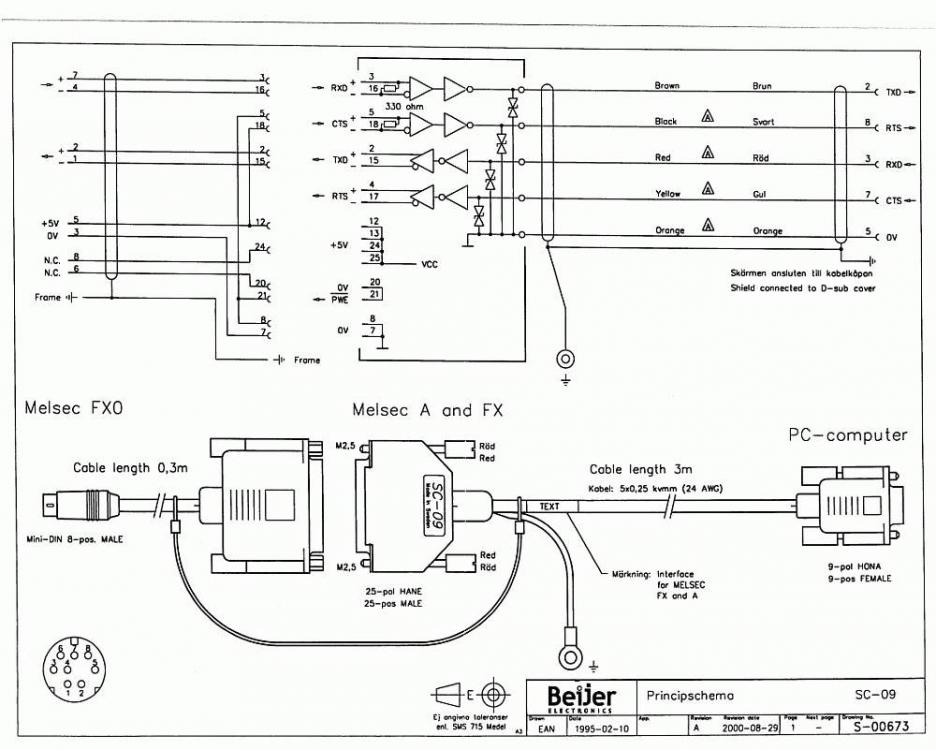
Ah yes...try this as well. The SC-09 is the connection cable for the A series and FX serial RS422 ports.
-
Try this startup guide for the 1020/1030 to FX. Diagrams from pages 3-7. Sorry, not familiar with the 930 enough to give you a comparison chart. Hope it helps though.
-
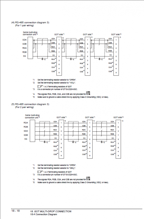
The following diagram might be what you are looking for. It was found in a communications manual that is available in GT Designer under the help tab help/manuals list (loaded if the Help files and manuals were selected at the time of installation of the software).
But if they were not, you can find them on the Mitsubishi website. Search for the manual: GOT2000 Series Connection Manual (Mitsubishi Products) Model: GOT2000-CON1-SW1-ELE or part number SH(NA)-081217ENG-N(1512)MEE
 1 person likes this
 -
Saleem,
Your abilities as an electronics engineer is not in question here. We are pretty confident that you know what you are doing. What Theo is referring to is that any electronic board wiring diagrams are proprietary information with Mitsubishi. They do not share these with anyone outside of their own repair shops and channel partners.
Regards
-

Here is a screen shot in case you cannot open the pdf
-
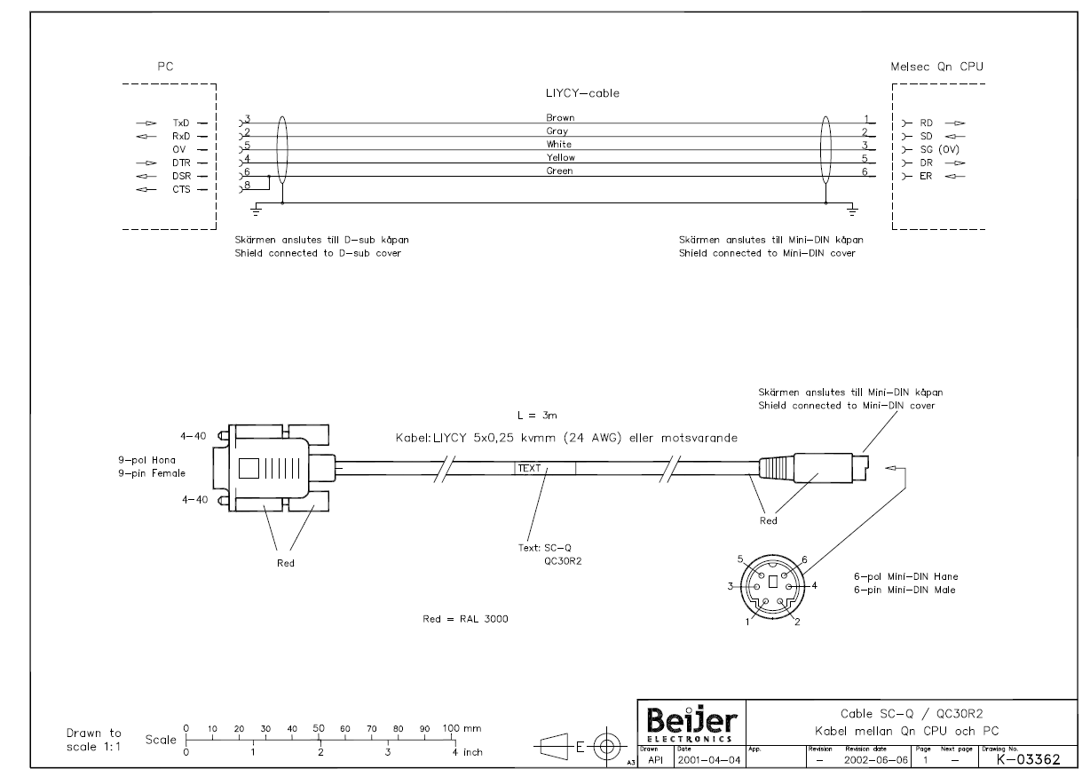
Lars,
Try this. It is the SC-Q wiring pin out for the Q and L series RS-232 port. Careful, there is an SC-09 cable pin out available which is for the micro FX and A series PLCs that have an RS-422 port.
1 person likes this -
On 6/23/2016 at 2:22 AM, Robo said:Thanks again Gambit for your reply.
Have made another request to Mitsubishi to obtain software.
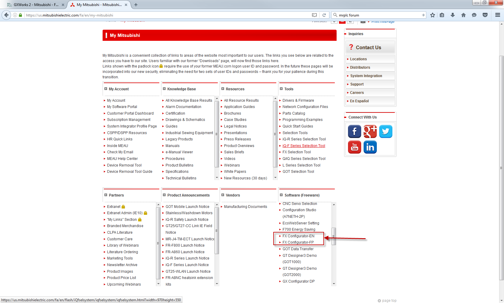
Robo, FX Configurator-EN is a freeware now and available on the Mitsubishi website. Log on and create a user account with password. Once logged in as yourself direct to the My Mitsubishi linked page and on the bottom right corner is a section called Software (Freeware). You will find that software there available for download there.

-
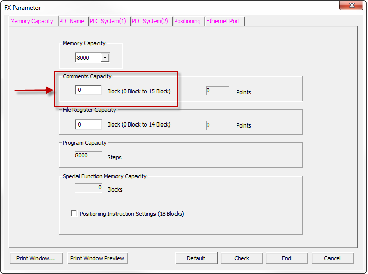
Each block added will allow 50 points of comments available for the program.
-
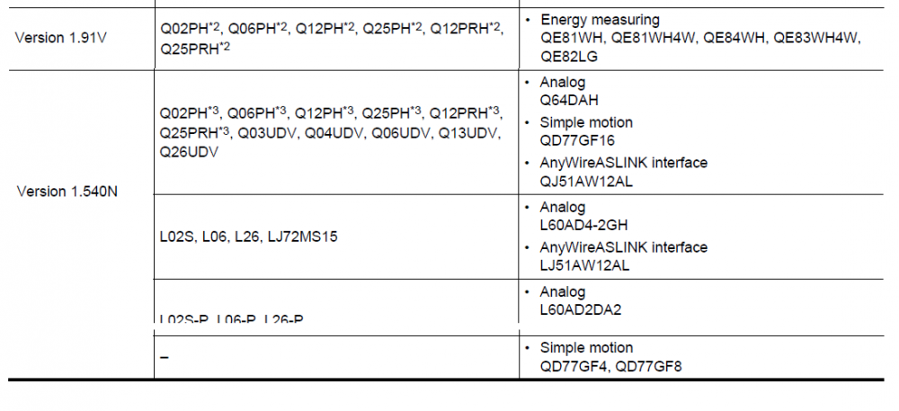
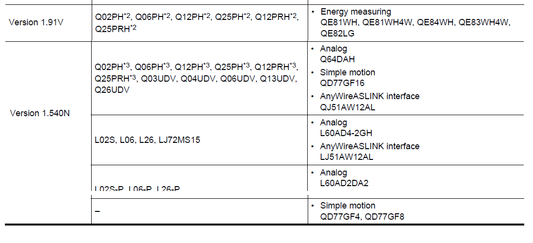
What is the PLC type the program is trying to read. Since version 1.91, which was the current version about 3 years ago, new processors came out and became available to program with newer versions of GX Works2. The following is a list of supported processors per software versions, taken from the appendix from the Programming guide for GX Works2.
-
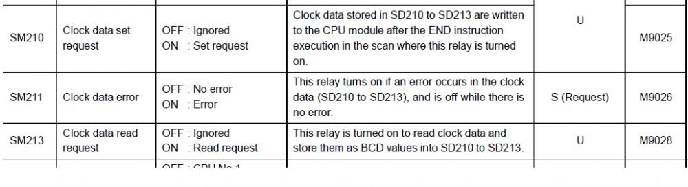
You will need to enable SM210 to update the clock registers SD210-213
-
Try checking the UnitID# for the Numeric Input (located in parameter settings Extended tab which is by default not enabled and value 1 when selected) and make sure this matches the Key code switch UnitID# in the button's properties (default value as 1).
The Unit ID is to match operation devices with each other when multiples are used per screen.
-
John_nohj
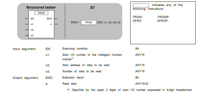
You are correct, by the looks of it you are reading this information from SFM#0, buffer memory location 10, 1 word and writing it into your PLCs Label iTTPosition. In function block form each address is entered individually in the fields provided with the block. And yes, I think that in FB format you would have to specify that SFM0 is a hex number and BM# is a decimal...I think. Someone please correct me on this.
The following picture is taken from the help files. If you put the cursor on the instruction in your ST program and press F1 a help window will populate with that instruction already loaded and with examples on how to execute it in the program.
-
10 hours ago, john_nohj said:The FX3G manual doesn't have a section for the FX3U-4AD, however it says the analogue value for the various other analogue modules are between D8260 - D8263 or D8280-D8283.
These addresses are if you are using the ADP modules that attach to the left side of the brick (FX processor). Their addresses are accessed through D registers depending on their mounting location. For using the FX3U-4AD, Special Function Modules attached to the right side, it is still in the U#/G# format.
The
;TO( ?BOOL_EN? , ?ANY16_s? , ?ANY16_n1? , ?ANY16_n2? , ?ANY16_n3? );
and
;FROM( ?BOOL_EN? , ?ANY16_n1? , ?ANY16_n2? , ?ANY16_n3? , ?ANY16_d? );
Structured Text instructions still work for these Special Function Modules.
-
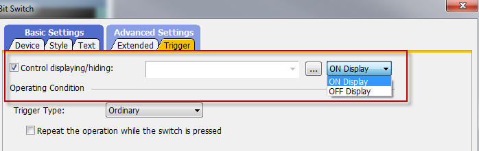
My bad DSev, WLla is correct. Scripts are not available in the 1020/1030. I failed to see that in your original post. But if you ever get to upgrade the HMI to a 2000 equivalent type model there is this Control displaying/hiding option for objects placed on base screens.
-
Good to know. I will keep an eye out as well.
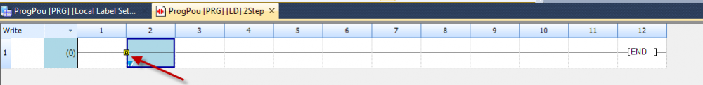
Sorry about that mislead with the edit line. I had that problem with GX Works2. I see that GX Works3 contains the edit line option on the work screen. Click on the yellow box and drag and you get the same operation as the old Edit Line.
 1 person likes this
 -
You can try the following script to make something visible when bit (M102 for example) is on.
VISIBLE ON BIT
if([b:M102]==ON)
{my.active = 1;
redraw_object();}
else
{my.active=0;
clear_object(); }
-
and the D in front of the AND instruction means this executed AND is looking at double registers (D720 + D721 AND H0FF will write the result back into D720 + D721)
-
No worries. These little bits got me as well when I started programming Mitsubishi
-
There is a free tool software on the Mitsubishi website that will help you with configuration of the FX PLC. It will give you the power draw and even addressing for added modules for the adapter side (right) of the CPU.
Click on the following and then click on the FX Selection on the first center tile (bottom right of the description):
What it does not provide is addressing for ADP modules. But for those the following convention applies:
First ADP module is to the left of CPU:
· 1st uses M8260-M8269 and D8260-D8269
· 2nd uses M8270-M8279 and D8270-D8279
· 3rd uses M8280-M8289 and D8280-D8289 (FX3U/FX3UC only)
· 4th uses M8290-M8299 and D8290-D8299 (FX3U/FX3UC only)
I suggest you read the module's manuals to see what these addresses represent, each module has distinct addresses.
1 person likes this -
Shift + Insert works with mine. Usually when I get that popup when trying to insert rows or Pointer addresses it is because I have the Edit Line option enabled. Check to see that you dont have any editing buttons turned on OR if you are in Read Mode (Shift + F2) put your editing screen in Write Mode (F2).
Just a few things on the top of my head.
-
Here I assume you mean the computer screen with the GX Developer or GX Works2 program running as the 'display'.
If you place your program in MONITOR mode the current value of the registers used in ladder logic will appear below the registers on the screen (typically in blue).


MELSEC Q2A PLC
in Mitsubishi
Posted
Open the front latch door of your Q02 CPU. The Compact Flash card is located on the left. There is a dip switch set to the right. If using the memory card then drive 1 needs to be configured on that switch. SW2=On Sw3=Off all other switches off.
Click on the link below for the full hardware manual for the Q02.
https://us.mitsubishielectric.com/fa/en/support/technical-support/knowledge-base/getdocument/?docid=3E26SJWH3ZZR-41-11833