

Akahige
MrPLC Member-
Content count
107 -
Joined
-
Last visited
Posts posted by Akahige
-
-
A CC-Link master module is a 32 point module. The error you are getting is that your IO addressing is overlapping. So if you have the CC Link module in slot0 addresses allocated to it is 00-1F, hence your first input module in slot 1 should start with IO address 20-2F (16 points).
By looking at your parameter picture the blue IO assignment tab indicates that something is changed from default. I am thinking that the Start XY field is filled out instead of allowing auto allocation. take a look at that tab, if a CC Link module is in slot 0(*0) its start address should be 0000, slot 0(*1) is the QX40(TS) starts with 0020. empty slot requires 16 points so 30 and finally QY-10 is 16 points as well so that starts with 0040.
1 person likes this -
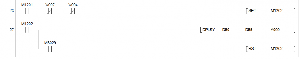
I see. When power cycle occurs you do lose the M1201 bit (as it is unlatched) and what I see is that when M1201 is active (assuming a start button) and as long as you are not in home position or over-traveled you request the pulsing of Y0 with whatever frequency stored in D50. And with a restart you lose M1201 so the pulse execution of Y0 is no longer active.
hmm...
The trap might work, but a power cycle also resets all set bits. Please let us know when you try this Saturday. Good luck.
-
It is. Try something like this:
-
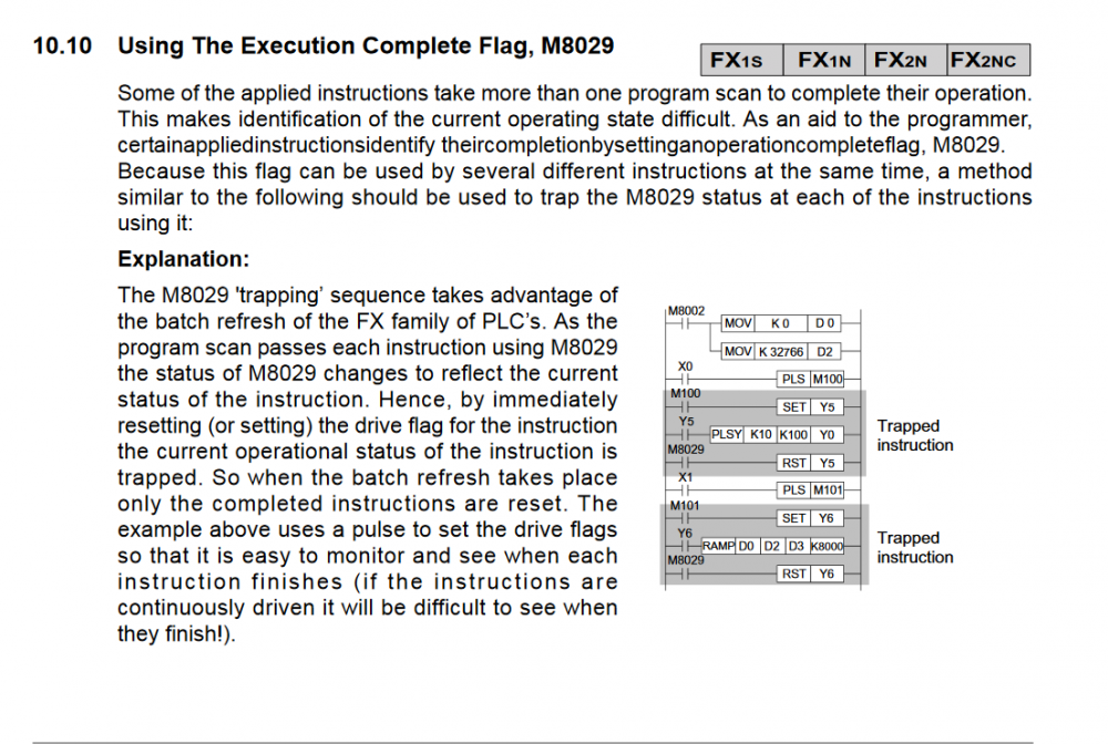
Yes, notice in the first example the instruction DSW is triggered by M8000 (always on) so that instruction has time to complete execution because of this and then M8029 triggers when the DSW is done.
On the second rung (similar to the one shown before) the DPLSY instruction may not complete before the next scan so the command input M0 needs to be SET on to assist. Once the execution is done, M8029 triggers and you are back to waiting to SET M0 with you discrete input X0.
The third example, well there is no instruction execution for the M8029 to reference...
Looking at your reference though, you might want to branch your M8029 like it is shown here. I see how this ties that special register to the executing instruction.
-
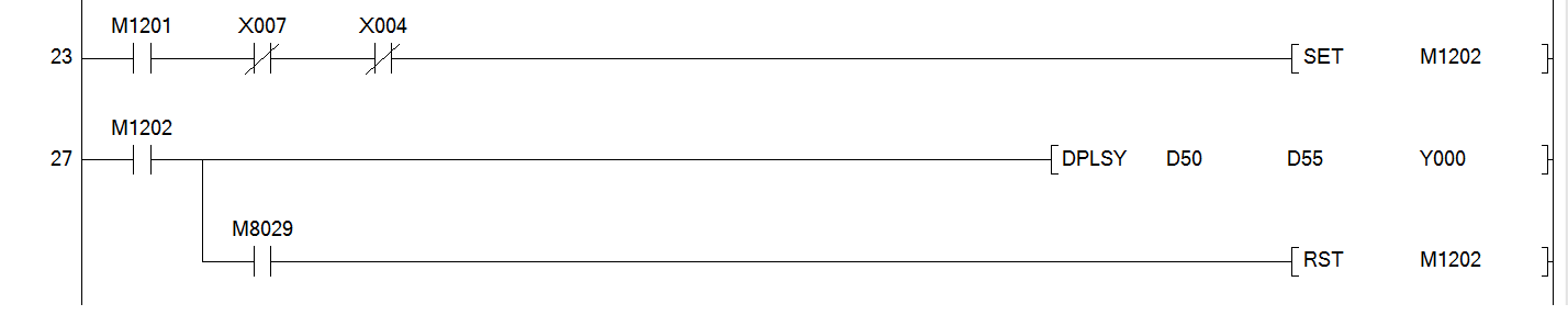
I do not see using memory bit M1202 being a problem @foxtrot99, the purpose here is to keep the instruction DPLSY active until the execution completes (and triggers M8029).

-
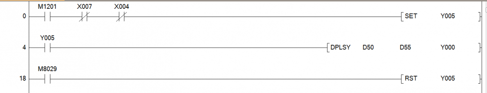
add an LDI Y005 RST M1201 rung after this to reset your SET RUN bit...just an after thought.
1 person likes this -
According to the FX Programming Manual II you need to set a trap to execute the M8029 for each execution.
Try something like this (Y5 is a general selection, I assume you can use any bit address)
 1 person likes this
 -
-
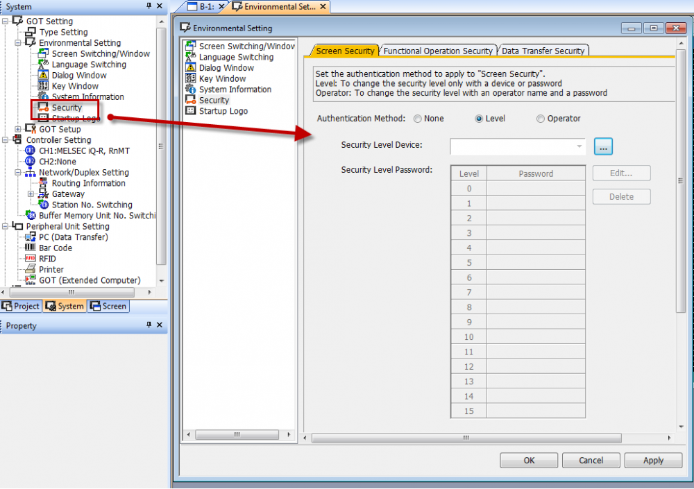
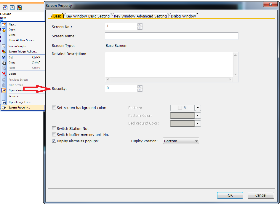
4 hours ago, Jana jagan said:Hi ,am using gt designer 3 software for gs2107-wtbd ., I need a help to set a password for a screen to access...
Jana,
In GT Designer3 open the System tab in the navigation window on the left. Expand the Environmental Settings folder and click on the Security option. In the resulting window click the Level radio button and you will get the option to create 15 levels of security (passwords and all).
With this done now when you create a screen where you can select the security level to access that screen inthe screen properties window.
-
@Andrei. I see you had rising edge Logging Bit command input executing the PLS instruction for the Log trigger. I always find this combination is tricky on long scan programs. Usually here you need one of the other.
-
On 6/9/2017 at 7:11 AM, Scott Gerber said:Hi -
We are currently running GX Developer FX at our College in the UK. We use this in the classroom to teach our students how to programme for PLC devices.
We now need to upgrade to a newer version that is compatible with Windows 10 - we are currently using version 8.03.
Scott,
Not sure if this is your issue but GX Developer is compatible with Windows 10. According to Technical Bulletin FA-A-0207 the .NET Framework just needs to be enabled. Look at section 3.1 of the attached bulletin. GX Developer is part of GX Works 2 so the .NET frameworks 3.5 needs enabling as explained in section a.
But if this is not your issue, I agree with the other posters. Get a current version of GX Works2. GX Developer is part of that software nowadays AND the revisions are still updated for GX Developer frequently. The latest version of GX Works 2 V1.560J gave me GX Developer V8.119Z.
-
Security levels can be created in the Systems tab by selecting Security under the Environmental settings.In here you can place multilevel security. Then when you create a Go to Screen button to access the created window in its properties there will be an Extended tab that you can select the Security Level to either display or input. The display will only show when logged in to the level. The input (screen switching) will only occur when the security level is selected.
Next create a Special Function Switch and select Password (Security Level) from the properties SP Function/Switch Action: This will place a button on your base screen that opens a keypad to enter the password for security levels created. So if the Go To button requires security level 1 to input the command the operator must log into security level 1 with the Special Function Key.
Hope this helps.
2 people like this -
Yes, simulators are useful for testing basic functions like triggers and discrete IO. Anything more complex is lagged. Like your timers.
-
Not sure if this is related, but I did run across this technical bulletin about installing GX Developer on Windows 10 operating systems.
-
Did you run the simulator in GX Works2 before attempting to run simulator in GT Designer. The simulator runs in conjunction with the Works2 simulator. You cannot run it separately.
-
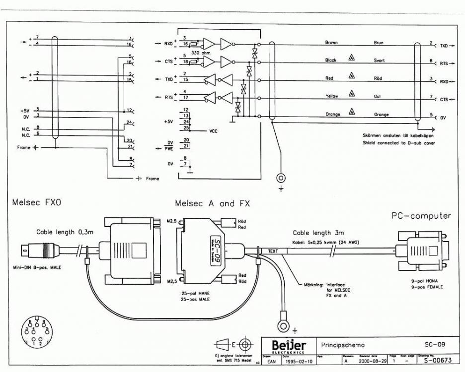
Smithers1
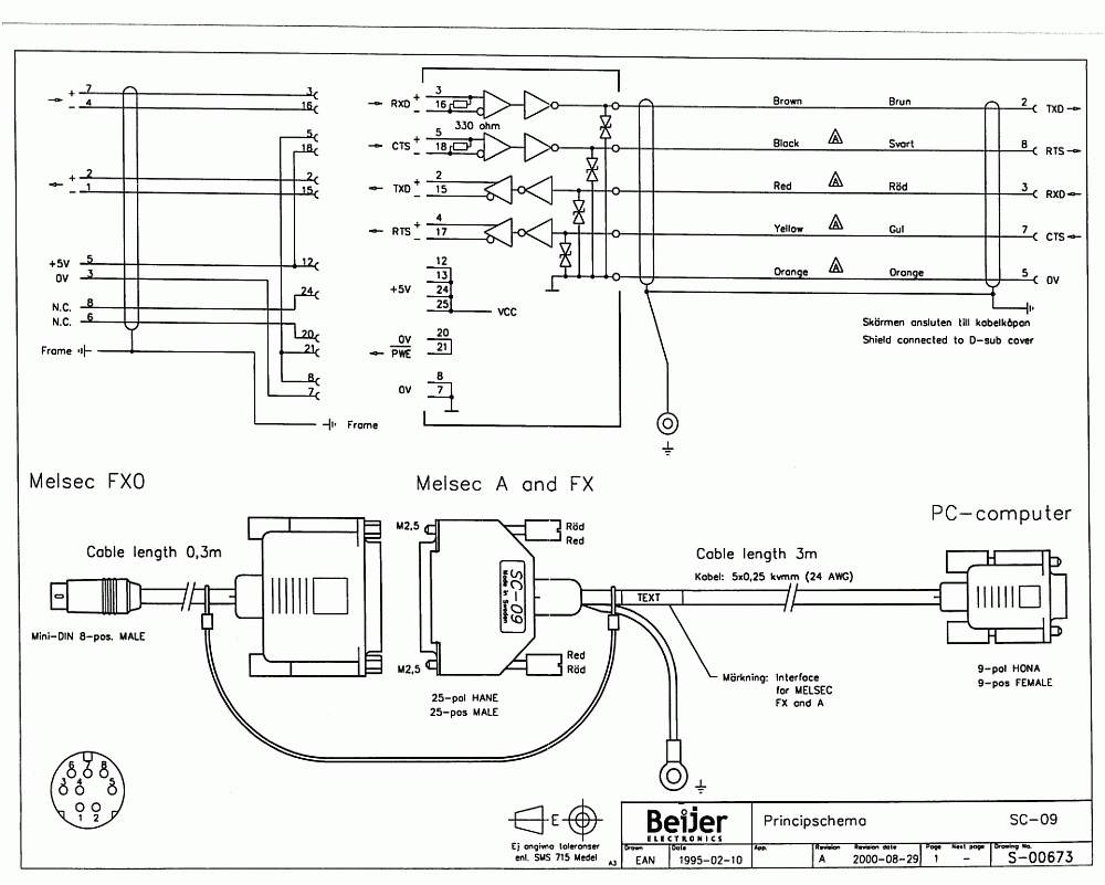
Try this diagram...if you haven't already figured out the wiring.
-
@Jonas80 Pardon the crudity of the logic but the following changes your requested word 102 into float 1.02
Changing from INT to FLT requires the instruction FLT. Remember that integers only need one register while FLT require two. So when MOVing an int value of 102 into D0 the FLT instruction stores 102.00 into D2 and D3.
Also because we are now dividing a FLT number the modifier on the math instruction (divide) needs an E in front and the reference floating number is now prefaced with an E (float) not a K (integer).
Our result of 1.020 is now stored in D4 and D5.
Hope this helps.
 2 people like this
 -
8 hours ago, titanspark76 said:The value oh D212 acts as the K value. Typically done when you want to allow a timer to be changed without accessing the program (from a numerical input on a HMI for example)
Correct. Instead of using a static integer as the timer's preset value the value stored in the data register is the referenced PV.
-
GX Works2 is the latest software that can program your FX3 CPU. It has options to create and maintain programs for Mitsubishi processors.
1 person likes this -
SD118 holds information of the station number in the PLC
-
The 1000 does come with its own battery for data retention when logging or alarming.
-
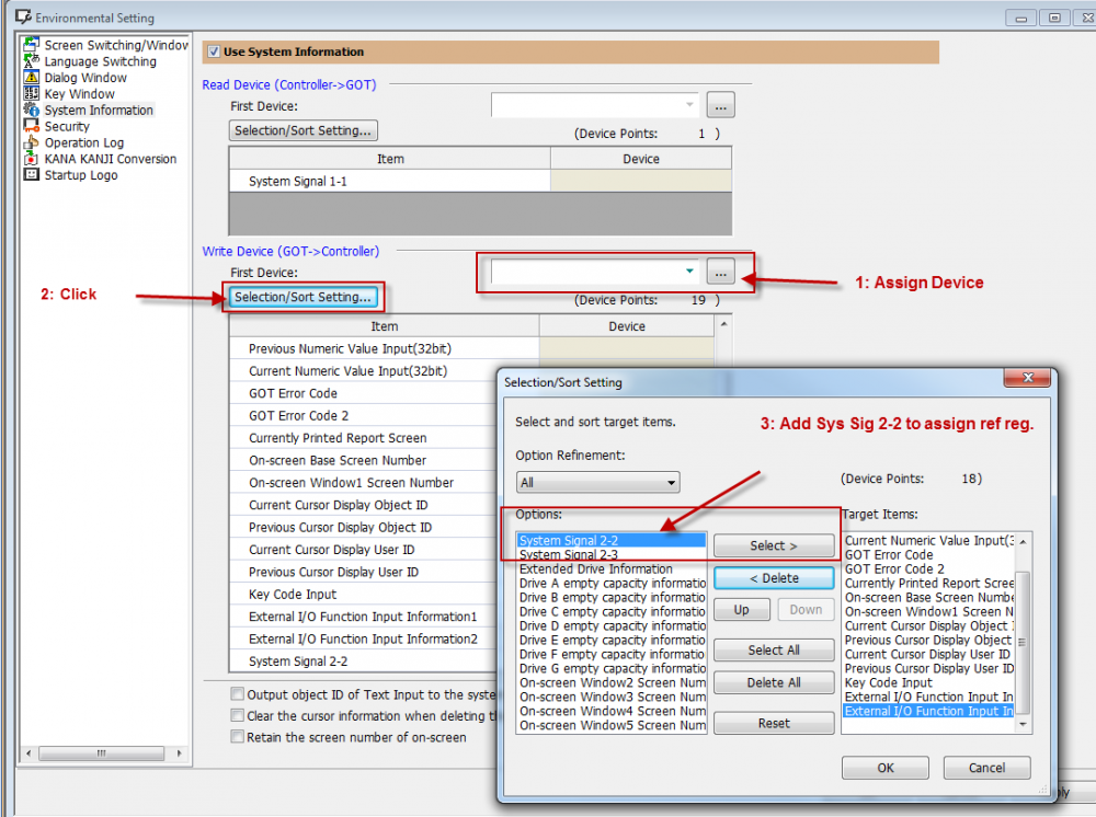
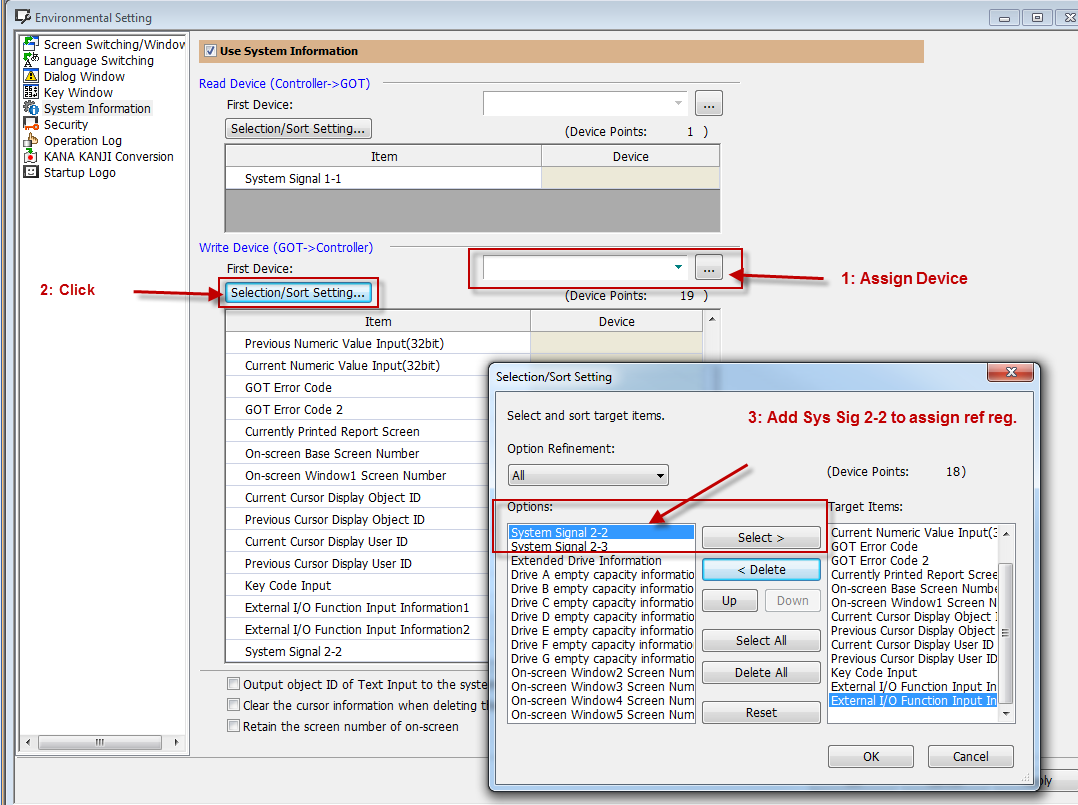
Which GOT are you using. For the iQ-R SD118 is reserved for (CPU) station number. it is not a GOT register (GOT1000 or 2000). If you require a battery indication device to reference on the GOT associate System Signal 2-2 bit 12 as its built in Battery voltage drop signal.
System Signal 2-2 is assigned in the System Information selection under Environmental Settings in the System Tab of GT Designer3 (assuming the HMI is a GOT 2000 or 1000).
-
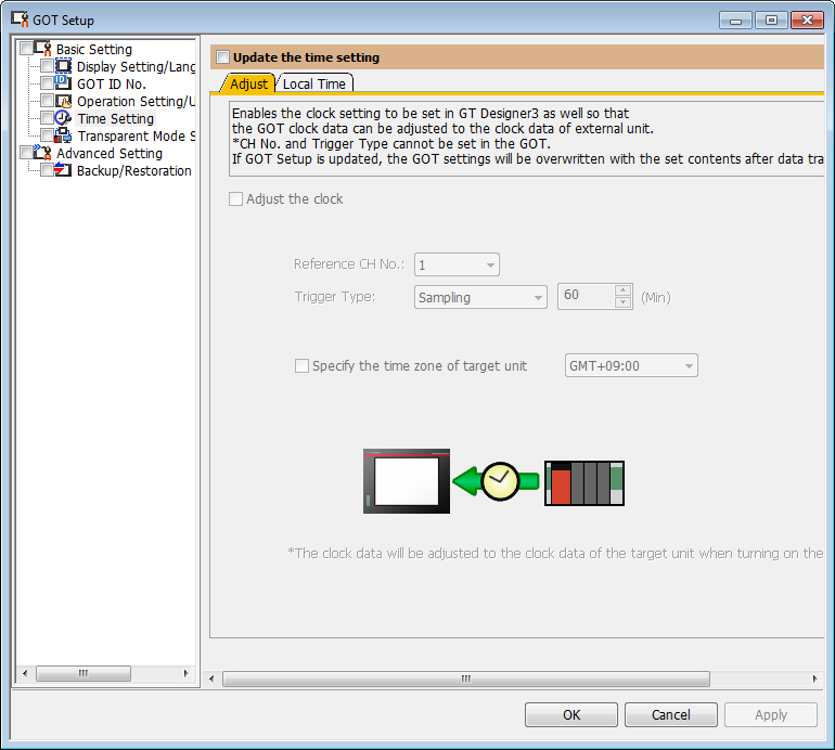
Under the Common tab of GT Designer3 you can find the time setting in the following sub directory
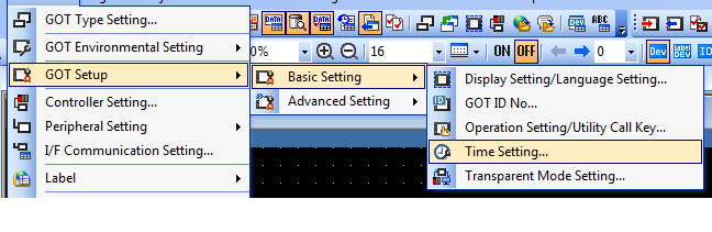
From here you can set link the GOT with the PLC or server so the time of one is synchronous with the other. What is probably happening is that either the PLC or the GOT have distinct time settings.
-
You can use the start button to start the pump and an hour timing circuit at the same time. Latch the pump running circuit with that timer timing latch so when the hour expires the pump stops. Ready to press the button once more for execution.
This usually works for any programming software. Depending on that software type the timing bits may differ.


Beginner Mk2.
in Mitsubishi
Posted
What triggers set cylinder extend Y30? This is what I see from your description: