

PLCMentor.com
MrPLC Member-
Content count
376 -
Joined
-
Last visited
Posts posted by PLCMentor.com
-
-
Kinda on the verge of hijacking the thread, but I guess it is pertinent poop for someone learning programming.
Took a quick look through your program and do have a couple immediate things that pop out:
- I never use conditional JSR rungs or at least I cant remember a time that I found one helpful. They are generally a way to get into trouble as all outputs stay in their last condition when you stop scanning the subroutine. The mantra in PLC programming is "keep it simple." This is a program just for you, but generally we are programming for the multitude of people that will follow us into the program after we are done. That is very unique in PLC programming. Generally in a plant environment the level of proficiency is fairly basic. Also at 3am in the morning when a line is down, brain functionality is fairly basic. Imagine the fun of seeing an output on in the program with all of the logic before that output false just because the program file is not being scanned at that time. Minds have been blown with less. In my experience, nothing good ever comes from a conditional subroutine. If you want an output off then put a contact in the rung to make sure it is off. Then the logic is clear and understandable to just about anyone. I suspect that is why you have to reset your outputs with the masked move statement. Another gotcha waiting to happen.
- I never use (or extremely rarely) the JMP instruction. That is a fairly common statement for all high level languages. Basic has its goto and just about every language has a statement to jump to a location in the program. Most instructors I have learned from will explain the statement and its purpose and then tell you not to use it. Those types of statements get you into trouble and are difficult to follow in most programming circumstances. There is generally another way to do the same thing. Same goes for MCP. That has some value possibly in temporarily taking sections of code out of service for testing or maintenance. As permanent fixtures they just cause confusion when people are troubleshooting.
- Rather than latches use seal in circuits. Latches generally cause problems. They are necessary if you need to maintain output status through a power failure. OTE's are reset when the system comes up. Same with the resets on your timers. TON's reset automatically when the logic before them goes off. Resets can be eliminated and everything that controls that timer's function then is on the rung with the timer. Thats much easier to understand when looking at the rung functionality. Side note: RTO's do have to be reset and are useful if the timer value has to be maintained such as for a total run time of a system that is starting and stopping.
- Even with the subroutines you have, I would move everything from file 2 except for JSR's to a subroutine. Leave file 2 just for JSR or insignificant overhead logic such as blink timers or such. That will make the logic much easier to go through.
- Looks like a fun project!
-
I have never used a display print function in Studio but I have had to get screen shots before. If you have Studio, then you can run in test mode on the PC and just take a screen shot of that.
-
Yep. Its located under the Tools menu option. Not sure if you have to choose to install it with a separate checkbox during the 5000 install. It's just always been available on my installs.
-
Mike's logic is a good example of the comparison method I mentioned. It is also offers a chance to talk about what I meant by using subroutines to organize logic. I encourage my students to get in the habit of using subroutines for organization even for small programs like this to practice and to get in the habit for larger programs. I would suggest that very little logic should be located in program file 2 of a SLC, micrologix or PLC5 even. Only JSR's to program modules if possible. In this program, you could put all the setup information in a program file and the actual control logic in a different program file. Not a big deal in this size of a program, but I think you can see the benefit in a system where you have lots of sub systems. Once again - PLC programming is different than other languages. Users will be in a PLC trying to troubleshoot at 3AM with only half their brain actually awake. The easier it is to get to the information they need the faster they system problem is fixed.
-
PLC logic has a little different mindset than other programming languages. So no to the subroutine for this. I actually find that subroutines in a PLC are more used for program organization than anything else. Take that in mind and try to come up with an alternative solution BEFORE READING MINE as the struggle to figure out the solution is one of the most important things to go through in learning to program anything.
That said... I assume from your text that this is an either or thing not 3 seconds for each 3 cars the sensor sees. The solution is actually pretty simple. You have a register that stores the normal time and one that stores the extended time. You then modify the timer preset with the stored values. It looks like this is total cycle time through all 3 lights. I would expect you would extend the green for the side with extra cars but not the red or yellow and obviously. if you extend the green on one side you are extending the red on the other side. If you use 3 timers the method I would use would be to copy the extended time into the green timer preset one direction and red timer preset in the other. An either or. Either you are copying the default time into those timers or the extended time into the preset for those timers. Of course you could do it all with one timer and just use comparison instructions to turn your lights on at certain accumulator values. You would still need to extend the preset time for your timer in that case also.
-
The applying changes notification does not refer to accepting changes on rungs that you may or may not have made. It refers to the software updating locally to match what is on the processor you are connecting to. I'm not sure what the dividing line is between having to upload to grab changes and it allowing it to apply changes, but it has nothing to do with rung edits you may or may not have made.
1 person likes this -
It's really not as bad as it sounds for versions over 20. You do have to install the separate versions; however, once installed you run the same program and you dont have to go through some selection process to use different versions. It's more like you install the capability to interface with different versions of firmware. Where it gets squirrelly (technical term) is when you have to work with a version 20 or below. Then you will need a separate software package (RSLogix5000 instead of Studio5000). The software will automatically switch between the required packages with those two also. So if you open something with Studio 5000 that requires RSLogix5000, it will automatically close Studio5000 and open the file in RSLogix5000.
1 person likes this -
Yes those scan times can limit or knock you off of online programming. Early on, I inadvertently changed my scan time at one of Rockwell's road shows to 1ms and completely locked myself out of the PLC. Had to take the PLC to program mode to be able to get online and change it back. The 3ms scan time is probably the one that is killing you as there is very little time in between for comms. You may want to see if one of your routines might be better served by an event rather than fast scan times. Rockwell does recommend using periodic tasks, but they do need to be setup with realistic scan times.
-
Are you referring to the S2 file with the first scan bit, error bits and such? If so there is not really a comparable group of data like that in the logix. There are ways to get information that is similar in the logix.
-
Thanks - I have no idea how the battery is being monitored, but I am purchasing the software to make sure I have a backup so I can check that out.
-
I have run across a Mitsubishi FX2N with a battery light on. I have never worked with Mitsubishi before, but the manual describes changing the battery and indicates the controller must be powered down for the change. You have to beat the clock and change the battery within 20 seconds. Has anyone changed these batteries while powered? Used to do that with PLC5's but I have never dealt with this processor before.
-
4 hours ago, Nyame Ephraim said:Hello Sir thanks for the contribution. i need to understand the ladder logic diagrams first. looking at ladder 5 you will see real world outputs as indicated in the electrical diagrams. now looking at the inputs of the ladder diagrams they are made up of registers , in this situation how do i figure out the real time input. coz if you check the input data file, it show some inputs are ON but i cant figure their locations on the diagrams.
Ok, a quick way to evaluate this is to go to your input data file and click on usage to see if any inputs are used. Doing this I see 4 inputs used in the program. I can right click on any of those inputs and select cross reference or find all and I will get information on exactly where in the program those inputs are located. I find inputs in program files 6 and 8. Keep in mind that the PanelView can also directly access such inputs so such inputs may be directly accessed by the PV screen.
-
The COP instruction is the correct instruction for this. You were on the right track with Array1[0] to Array2[0]. You just need to put in the number of elements to copy as the length. You cant leave off the [0] part as the starting location. Array1 is not a valid location - Array1[0] is.
2 people like this -
So if that is the PLC program that they forwarded to you then that is unfortunate as it also does not have any descriptions in it. I would again request they send you a copy of the program with descriptions. If you get it, make sure you put it somewhere safe so that it will be available in the future. In addition, I would ask them to send you a copy of the Panelview configuration or backup. With that you can restore the existing HMI configuration to a new Panelview. While panic is a little harsh, his primary points are valid. I understand that your facility probably does not have experienced controls people that might have been aware that this was an issue. Now that you do understand this, I would suggest you go through your plant and catalog other machines that may be lacking proper documentation. Get ahead of the next problem by making sure there is a documented copy of each program and configuration files for all of the configured electronics in your facility. On this system, if you cannot get a documented copy of the program, you at least have a copy of the drawings so documentation can be added. Your fist step there is to go to each input and each output in your program and add the description shown in the electrical prints. Nobody on this forum is going to do that for you. They will answer questions and some may be willing to take care of it for a fee. I would suggest locating a local integrator to help you work through this issue. It sounds like you really need someone to look over your shoulder as you work through this.
1 person likes this -
Ok I'm not really sure what the exact method Ron proposed way back when as it is no longer available. In fact I'm kinda surprised that his posts all have "Guest" by them. All of that aside, they do discuss something that I was going to suggest you try and it looks like one person has used it successfully in the PLC5. Keep in mind that as we have mentioned earlier, all memory locations associated with OTE instructions will be reset upon power up or return from program mode. The way you may get around this is to store all of your outputs in INT tags continuously in order to save their operating value. Upon return from power up or run mode, you would use the first scan bit to copy from those storage registers into your output registers effectively restoring the output word values to your outputs. Obviously this move instruction would need to be processed before any output instructions to work properly but otherwise it should work. I've never tried this before and it sounds like a good way to get into trouble from a safety point of view. You generally dont want things starting up from a power outage without some sort of operator intervention. If you only have a few outputs that you need to do this with you could use a masked move to only enable the outputs you are interested in restoring on power up.
1 person likes this -
I'm not sure what you are looking for, but I see a program with absolutely no documentation. That usually happens when someone uploads from the PLC without having an existing program file on the PC. Until recently with the later Logix controllers, all documentation was stored in the program file created in the programming software. Uploading without that will just give what you have shown. I would suggest trying to find an existing program file on a PC. If this was contracted out, you may be able to contact the integrator. Most of us keep files from our previous projects. Other than that, your only option is to go to (hopefully existing) drawings. You will have to methodically go to each real world input/output and document their purpose. From there you have to work backwards in the program determining what each register and bit does and documenting along the way. I did notice real world outputs in ladder 5 and many of the N register bits are just buffer bits and directly activate those outputs. Figure out one and you get the other! Two for the price of one. Unfortunately this is a long and drawn out process that could take days to complete. In addition, without information on the real world I/O there is no way for anyone to really be able to help you figure out what does what. Unfortunately you have a lot of work ahead of you! I'm sure if you get stuck anyone on this forum would be happy to help. The program looks to be fairly straight forward so you dont have to worry about complexity. Could be a good learning experience. I'm sure that's what you wanted to hear!
-
Keep in mind that you will need to pair each OTL with an OTU (latch and unlatch) in order to turn the output off.
1 person likes this -
Yes you can change the value of a data table item by placing your cursor on the value in a statement as you have shown and just changing the value. As Armadillo points out, you should do a cross reference of that value to make sure it is not overwritten somewhere else. Keep in mind that it may be overwritten conditionally and may not immediately overwrite the value you put there but may do so when required by other logic.
-
Yeah I'm not sure about that. We have a custom AOI where I am using this so it would not be the same. If you are using a Yaskawa AOI, then it should be documented in one of their manuals. It should not care about the size of your drive or any about your motor characteristics. That is all stuff that is configured in the drive. You just care about start, stop, speed, faults, etc.
-
Not too familiar with the 5/01, but that sounds like you have lost the program. Can you go online?
-
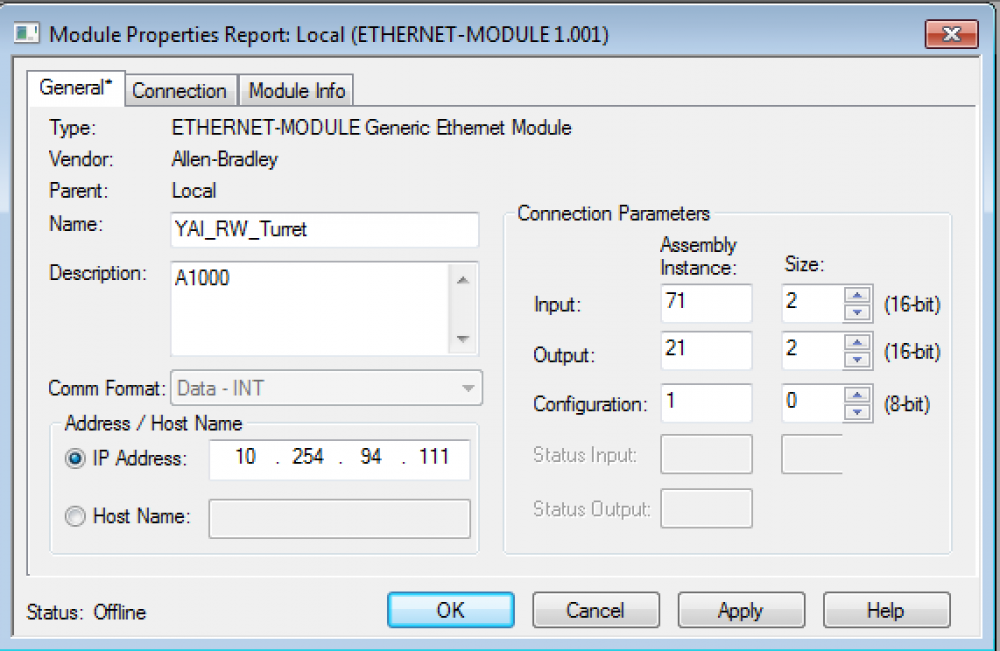
What AB PLC are you using and what Yaskawa drive? Third party drives are actually pretty easy to setup on the logix platforms also - you just need to use a generic ethernet module. All the settings in the module are in the Yaskawa Ethernet I/P manual if you are interfacing with a compact or controllogix. You will have to get out the manual to discover the best way to start/stop and control speed as well as how to get feedback information. Attached is an example of the Ethernet module setup for the A1000. Pay careful attention to the comm format data time. Choose the wrong one and you will have problems. Not that I have ever done that....
-
Given the age of your system, I wouldn't be surprised if the power supply was already going. They can die in weird ways and one of the things that can happen is that the PLC will drop the program. Not real fond of the SLC power supplies as they can cause pain and suffering. They don't seem to just die and that's it. Every one I've dealt with caused weird problems such as program drops that went away when the power supply was changed.
-
Sorry I have to respectfully disagree on this. There is nothing that can be done with the OTU in the situation you mention that could not be done on the rung with the OTE.
-
I agree that are uses for the OTU with HMI and SCADA interfaces, but there would be no need for an OTE in such a case. In addition there should be one OTU with all the conditions grouped on that rung. That's why OTL/OTU's can be evil! People place them all over the program and it ends up making one giant mess. Unfortunately he probably has one of these programs that has evolved over the years with a little here and a little there programming and no attention to the program as a whole. Nothing like the patched patch of a patch to make your day interesting.

My Model Train Project
in Allen Bradley / Rockwell Automation
Posted
Well I have to say that you get the planning stage much better than many coming to the PLC programming field. I see experienced programmers that see no need for any planning document or specification. I would assume that comes from your previous programming experience. You have put together a basic plan for program operation and detailed your I/O. In a real world project a detailed functional specification is recommended. It takes time and effort and is not really completely necessary in full detail to successfully program, but it is necessary to successfully define to a client or user of a system how you as the programmer and designer of the system see the system working. Many wrong directions can be figured out early with a good document. Well.... if someone reads it - but that's a different discussion. I put a video on youtube a couple years ago on this. Wasn't real popular as people want to program not plan. Here is a link: https://www.youtube.com/watch?v=FedqCBDy-fU&t=33s
You should be able to find lots of information by googling seal-in circuit; however, we have an old article on ladder logic that shows one about half way into the article:
https://www.plcmentor.com/Articles/PLC-Tutorial
Essentially you "seal" around the start pushbutton to maintain the output. Our article show the seal using a contact off of the output. Generally with a motor seal in you use the AUX input from the motor starter as your seal. I always use both the output and the AUX to seal in my motor circuits due to an experience with a faulty PLC5 I/O card that caused my inputs to cycle on and off for no reason. Nothing like hearing every motor starter in the room cycling on and off together to make an impression.
As for how to start attacking your program I generally look at it like this.
Keep in mind with a controller like the micrologix, slc or even PLC5, AB makes it really easy to organize your data similar to how you organize your program files. You can create bit files or integer files (and others of course) for specific purposes and have organized data as well as program files. My general rule of thumb is not to use the generic default data files for anything other than extraneous data that just doesn't fit with anything else. I always create data files to fit my program needs. How you organize it is up to you. Just do so!
The micrologix 1100 and 1400 are both great little processors. They both have ethernet ports that can be used for programming and the 1100 can still be programmed with the Micro Starter Lite. Also both allow online programming which is an essential tool in real world programming. We dont take a system down to make small changes to the program in production systems. Might as well practice that way also.
Hope this all helps. Have fun!