

PLCMentor.com
MrPLC Member-
Content count
376 -
Joined
-
Last visited
Posts posted by PLCMentor.com
-
-
18 hours ago, pturmel said:What you are asking is fundamentally a role reversal for SCADA/Historian designs. PLCs have known protocols allowing external systems to interrogate them and perhaps write supervisory instructions into them. WW and similar implement the PLC protocols to interrogate the PLC. The PLC can't interrogate WW. Generally, at best, you can use supervisory control writes into the PLC to increment a heartbeat register or set an "I'm alive" timestamp.
That's exactly the thought had when first reading the post. I don't know if historian has the capability to write to the PLC as it is generally designed to just poll for information. Noorloai, can you go back to your Wonderware tech support and see if historian has the capability to write to the PLC and perform some simple logic. The aim would be to create an on/off hearbeat at a set interval (ie, 1 sec on and 1 sec off). If you can achieve that then you can analyze that bit in your PLC by using timers. If the bit from the Historian stays on past one second or off past one second then the communication is considered lost and you can act upon that however you want in the PLC.
1 person likes this -
Evan - we have about 9 hours of wonderware training on our site that may be useful. It was done in version 10, but most of the information still applies to later versions.
1 person likes this -
There is also a 7 day grace period when you install the software. If this is a quick look and done, you can probably just use that if you have access to the software installation files.
-
I would be interested in hearing a bit more on this when you swap some things around. The class 3 msg has to do with HMIs, SCADA and other unscheduled communications including uploads/downloads. It may be that swapping things around as pturmel mentions will clear things up. One thing I saw with a quick google was people saying that firmware versions < 32 seemed to have issues with locking up class 3 comms. I don't have any direct experience with this so just passing on what I've read. Either way please update this thread when you have moved things around a bit.
-
On 9/17/2021 at 9:02 AM, Joe E. said:In CompactLogix and ControlLogix PLCs, double-click on each I/O module (whether local or remote) to open the properties. On the "Connection" tab, check the box next to "Inhibit Module". The code will run like normal but the I/O will be ignored.
Edited to add:
You can also inhibit/un-inhibit modules via SSV instructions, but I've only had to do that once. One cool thing you can do while the input modules are inhibited is write to their tags. I've often written simulation programs to run alongside the main program to test my logic. So, for example, when an output turns on to move a cylinder, there's a time delay in the simulation program that will then turn on the input associated with that cylinder's position. It makes it a lot easier to commission a system when you've already simulated the logic. When I can simulate it ahead of time, I can typically just do an I/O check (make sure they're wired correctly and physically work) and it runs with little difficulty.I do this with pretty much every project I put together. I have a simulation mode that my system can go into that runs the routing that sets all of my i/o to inhibit. It also enables the JSR that runs the logic to simulate inputs, puts my scaling blocks into a simulation mode, etc. Its really great for batching systems as you can make sure everything works well as the system sequences through the batching steps.
-
Kollmorgen has an Ethernet I/P version of their drives that is fairly easy to connect to and their support is good. Unfortunately you will probably have the same supply problems with their equipment as you are having right now.
-
Ok now that everyone gets how it works the original question was why would you use it.
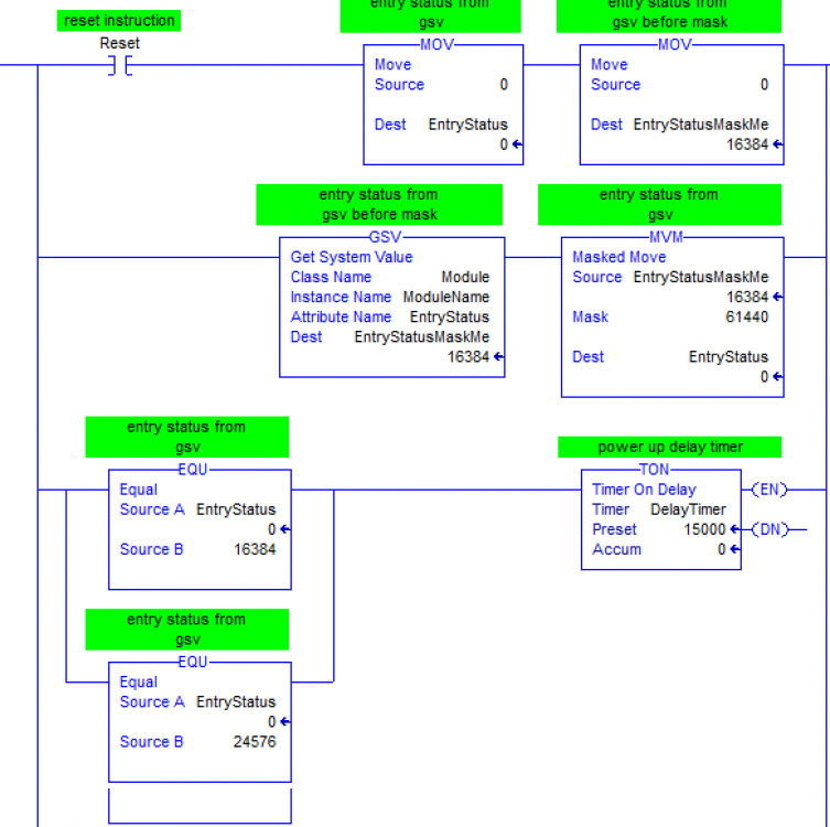
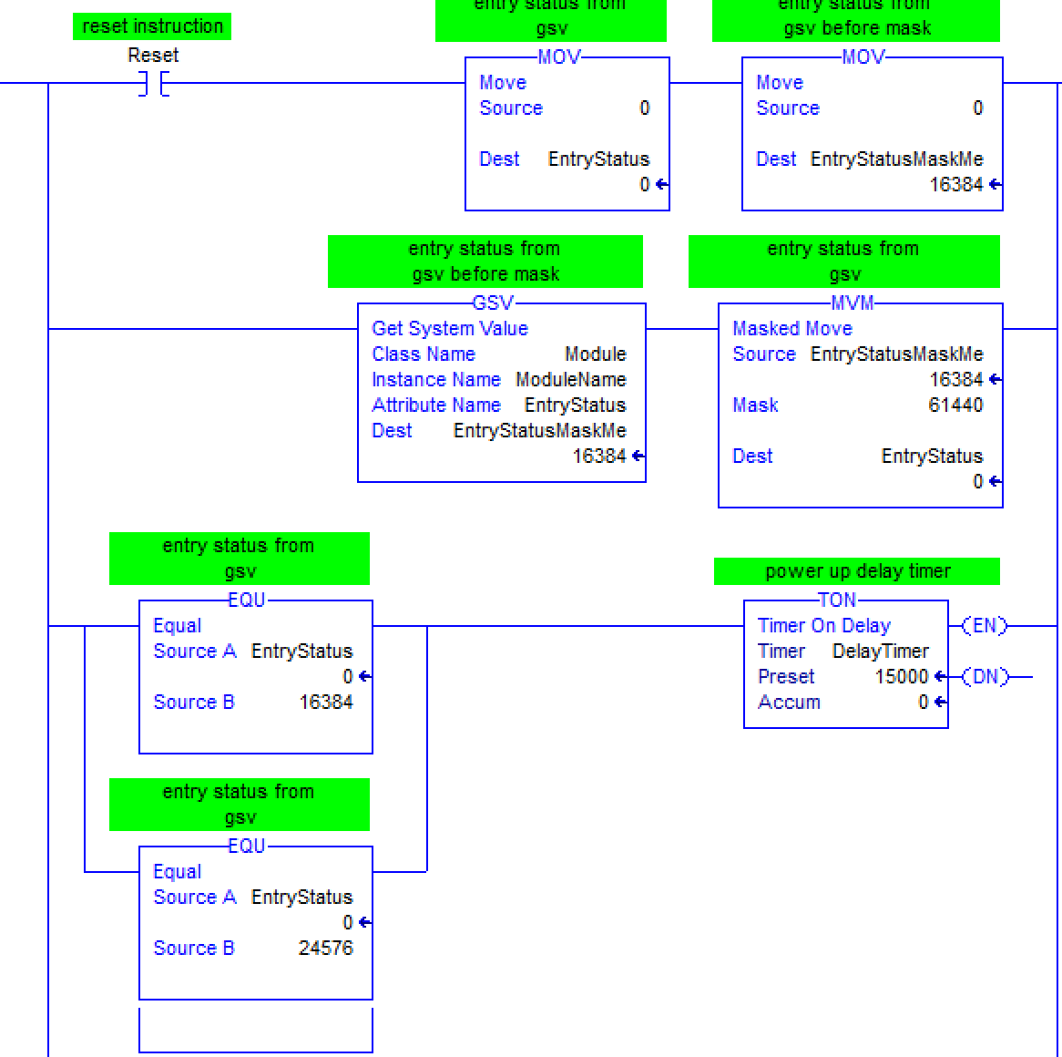
Generally I have used this instruction to sort out information from communication with a non AB device or a blob of data from some other device. For instance if you have a DINT where not all of the bits are pertinent poop, you may mask out the unnecessary stuff to make it easy to do comparisons. I use this in conjunction with some GSV statements that store certain data in 4 bit lumps. I can mask out everything else and then do simple comparisons with the result. I actually think I got this right out of the book for checking comm status on system modules. Granted, in retrospect, I could have just done the comparisons using bits... But mine goes to 11 (maybe someone will get that reference).
 1 person likes this
 -
I'll put another vote for the RedLion HMI's. Simple to use and will connect to about anything. I will say that they are hard to come by now with all of the Covid delays going on.
-
As Joe mentioned DH+ is pretty resilient to abuse. If you are removing the last PLC in the line, you can still just unplug the PLC and leave the connector, term resistor and all until you can properly modify things. Once you dont have to worry about things going down, you can remove the cable from the preceding device and place the termination resistor at that location. Just as a side note, DH+ actually had a more complex installation method of station connectors and drops off of the trunk line and a very specific cable that needed to be used. In actual practice people found that it was easily daisy chained without any problems to service. Not having the right cable can be a problem in certain instances and not having the proper termination resistors can cause issues also, but usually people can do lots of stupid stuff and still have an operating network.
-
It seems that copying an empty string solves the problem and is simple. Is there a problem with that method that would require any of the other methods discussed here?
-
Gotta agree with the learning ladder. That said, program to your audience. If you have a staff of computer science experts then maybe structured text is the way to go. Generally with PLC's you are going to be working with a maintenance staff with electrical knowledge and those guys are who ladder logic was developed to make things easier for. As Bob said, you can do a lot of advanced programming with PLC's now days. It's generally better to program things as simple as possible in order to make things easier for those with less programming capability than you have. Also, at 2AM my brain doesn't operate well enough to remember what all that indirect addressing was doing! So in reality you are programming simple for your brain at stupid hours when it needs things easy too. In PLC's often simple, repetitive, well organized with good documentation is better than optimized and compact.
-
Looks like the software is in the Downloads/Demo software area. I tried to copy the link:
https://forums.mrplc.com/index.php?/files/file/868-rslogix-500-micro-starter-lite/
-
I'm not sure whether F10 still applies or if that was older software. The steps prior to that - Monitor S:6 to determine the fault - will require getting online with the software. RSLinx is the communications interface, but you will need RSLogix500 in order to get online and view the program and check that status word. RSLogix500 talks to RSLinx which talks to the PLC. For the Micro 1000 there used to be a freebie package available. It used to be posted on this forum.
-
When you said they could download the program with RS500, does that mean they could open it in offline mode? What messages did they get? I would think if they could download it with the software they could edit it also. I think there is some missing info here.
1 person likes this -
Mickey's going old school! Used to be the way we had to handle floats for some processors. Glad those days are past, but that is a valid way to use integers. The problem that I think you will have with the micrologix is a 256 max data table. I think you can only have 256 elements in each data table. Maybe mine is old. If this is a problem then you will need to split your 365 elements into 2 different tables. I would suggest that you could use indirect addressing to move your values directly into floating point registers. When your index is greater than 255 then enable a different move that points to a different table. Something of the format: F8:[N7:0] where N7:0 is the index of the element in your F8 file.
-
No problem. Hope it helps. I cut my teeth on the PLC5 and never had the opportunity to work with the PLC2, but a cross reference is a cross reference. One of the things that has changed since that time is the mobility of the computers. While I never worked with one, I had plenty of sites in my early years that had one and usually they had a large terminal right at the PLC for modifications. If you wanted to look at the program anywhere else, you used the printout. Now with the more mobile computers, it makes more sense just to learn to work within the software instead of prints. The searching capabilities and speed of the newer computers all combine to make this much more efficient. There is a mental change that you have to make to take this step. I would suggest moving over to the computer for searches and other such operations. It is a big mental step when you first go from the prints to the software but well worth struggling through. The newbies never dealt with this issue as they always have used the software.
-
I'm having a hard time with the open circuit with slightly under 4ma. I reread his post and he does specifically indicate that he is receiving an open circuit condition. That throws out any underrange condition that I veered off course on. Maybe the power supply is wigging out (technical term) or maybe the card has problems. I would not assume a processor fault just because the machine goes down. The open circuit condition makes the input value fail high or low and that would very likely trip a limit in the program to make the machine stop. If I remember right, the manual says that the open circuit function is only operational in the 4-20ma mode. That would be another reason to try the 0-20ma just to get away from that function. Keep in mind that you may have to do some rescaling. I would also add some logic to check if the input is dropping out (maybe less that 2ma). Just because you cant see it while monitoring doesnt mean that the PLC doesnt see a quick dropout that is more dramatic than 3.96ma. A rung with a LES and a latched bit would be a simple way to check if something is happening that you are not seeing from the programming software.
1 person likes this -
I cant find in the manual where the open circuit function is looking for the input to just go below 4 ma. That doesnt make sense. What would the underrange bit be set for? I think the open circuit function is just that. It looks for a load and if it doesnt see one then it alarms. If it was just looking for a below 4ma condition then a quick work around would be to setup the inputs as 0-20ma, but I've used this card in the past and not had this issue. It's not unusual for a transmitter to send a value of 3.95 or such at the low end of its range. Generally the 4-20 inputs will read slightly below 4ma and slightly above 20ma. I would still check the logic to make sure its not programmed around an underrange bit. If it really proves to be the open circuit function causing the problem then you may have a damaged card or field device.
-
I never really print programs any more. It's generally best to get used to just getting around in the software and using the cross reference function in there. A printout can be very big. I thought I would just test with one of my current programs and I gave up after it was showing 1000+ pages and wasnt even a tenth of the way through. That said, the answer to your question is yes. The cross reference will look very different as you have tasks/routines and programs as well as different programming languages other than ladder. In the print setup you can go to the tags section and select to print the cross reference. It will look something like this for each tag:
CoatPumpB.ManMode 0 BOOL
Coating Pump B Drive Interface Mode Select 0=Automatic 1=Manual
CoatPumpB.ManMode - VatRoom/CoatingPumpB - *5(OTU), 10(XIO), 6(XIO), 8(XIO)First line is the tagname, value and type. Second line is the description and the third is the cross reference. VatRoom is a program and CoatingPumpB is a routine. You can see the tag is used in an OTU on rung 5 and so on.
1 person likes this -
I wouldnt think almost 4ma would present as an open circuit. It may have an underrange bit that could be being used.
-
This is just a copy of my reply to your PM:
Your application sounds more commercial than industrial and is not really part of my experience. I can offer some advice. Every SCADA package demos well. It's not until you actually start working with it that the deficiencies come out. Find users of your top picks and quiz them. Also see if there is demo software available and try it out.
-
Well I believe they think they are. They even have a manual that covers part 3 of the standard. Unfortunately my understanding is that the standard is so loosely defined that compliance doesn't actually mean much. Not like you can take a siemens program and load it on an ab.
-
When you setup your generic Ethernet module, make sure you select the correct data type. This has snagged me more than once (sorry to admit). It's very easy to forget and use the defaults and just fill out the number of input/output and config words. I believe it will show a valid connection on many devices, but the data transfer will be messed up.
-
I am very partial to the Inductive Automation Ignition platform. Am using it with contrologix, plc5, slc etc right now. I would suggest conerting your connection to your Modbus/rtu network to an Ethernet based interface. Ignition is a server/client based system and ethernet is much easier to connect to. Moxa sells some great little gateways to allow connections to legacy networks like that. You mention desktop, but if you are interested in a local HMI then I would suggest RedLion. Also connects well to the logix.
2 people like this
SELF -Educational books or CD
in Allen Bradley / Rockwell Automation
Posted
You might check this out:
This looks like it's a lab guide. He also has a PDF text on PLC's. Most PLC books I have seen try to go about it with generic knowledge (ie, not a specific PLC type). You then end up with generic knowledge that is useless. Well, unless you just want to kinda understand what a PLC is. I feel like you need to pick a manufacturer and learn on that platform. Then you will actually have some practical knowledge.