

Mendon Systems
MrPLC Member-
Content count
490 -
Joined
-
Last visited
Posts posted by Mendon Systems
-
-
I have used the Teco SG2 PLR for a few panels and have never had any failures with them. They are similar to but a little bit less expensive than the Idec units. Their tech support is not great, but that's to be expected with a cheap controller. Their analog I/O module has a very limited analog ramp capability (4 fixed steps), but probably enough for what you are doing.
http://www.factorymation.com/Products/Programmable_Controllers/
The other alternative would be a low end "brick" PLC like the A-D Click or the Omron CP1E. They're more expensive, but have better support.
-
3 hours ago, Katerina said:Thank you for your answer! What do you mean by saying''NO contact of the appropriate flag (<, <=,=,>=,>)'' ? Is that what you told me to do? (see the picture)
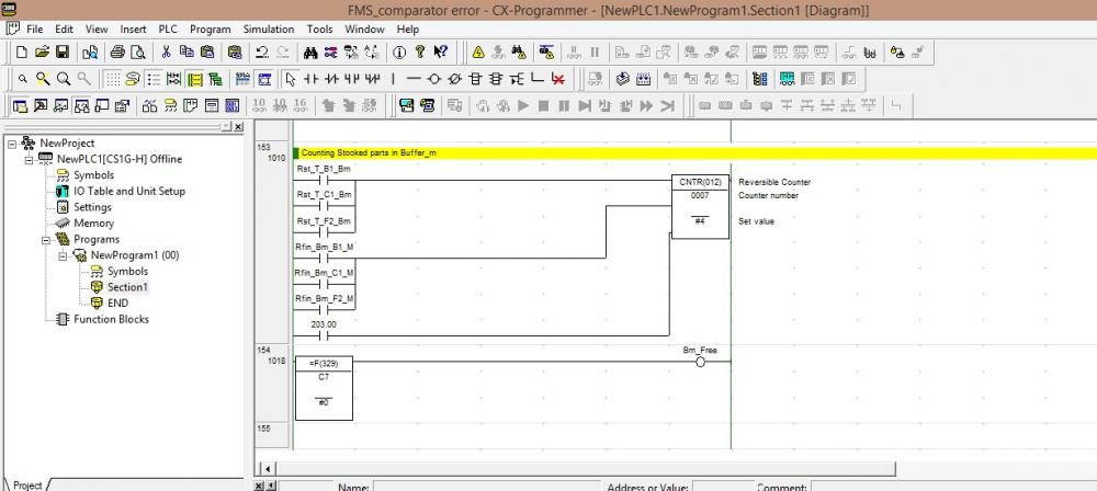
The method that you have used in your latest code sample is the simplest way to accomplish what you want. The symbol math instructions (called "input comparison" instructions in the older CJ1/CS1 manuals) will do everything in one instruction.
The CMP instruction requires you to use the processor flags as shown in IO-Rack's example. It does have the advantage of being able to check for all three conditions in one rung, but you must be careful to do the condition tests immediately after the CMP is executed so that nothing changes those flags.
-
The CMP instruction sets one of the arithmetic flags in the A memory area. You need to use a NO contact of the appropriate flag (<, <=,=,>=,>) in rung 155.
It is probably easier just to use the corresponding symbol math instruction (<, <=,=,>=,>) and forget the CMP entirely.
-
AND .... you'll probably need to do a little bit of simple math also. Just converting to BCD is only going to give you timer presets from 0 to 15. You'll most likely have to add 1 to get a range of 1 to 16 then multiply that by some constant to get the right timer scale.
-
It seems as though you should be able to use the MOVD(83) instruction to copy those bits into a DM register and convert the register value to BCD for the timer preset.
-
Mechanical switches typically do not repeat as accurately as photo-electric sensor or prox switches. That's probably not an issue for the travel limits but it might be for the home switch depending on how repeatable your positioning needs to be.
-
Generally that is the correct approach, but most slides use 3 sensors. They typically have two NC travel limits and one NO home limit located just before one of the travel limits. The procedure for finding home is essentially what you suggested. Finding the other end of the travel may not be necessary because it is a constant. Once you know where the home position is, you can calculate the other limit.
-
-
Well ... I think I have figured out what they (MLPX, DMPX) do. The MLPX instruction sets a bit in the result word(s) based on a hex value in the source word. The DMPX sets a hex value in the result word based on a bit in the source word(s). Here's a very simple example:

-
3 hours ago, Idir said:Yes, the serial to USB adapter works fine because I succeeded to communicate with two other Omron PLCs with different cable ( but same adapter). Now, Could it be the cable shown above that might be problematic?
That is not necessarily correct. I have had more than one occasion where a USB serial adapter that worked fine with other Omron PLCs but would not work with a CQM1. The CQM1 serial ports are temperamental at best.
-
I hope they have a backup copy somewhere. There is a lot of useful information that has disappeared!!1 person likes this -
It is going to depend a LOT on exactly what you mean by automation. If you are just looking at analog signals you can probably get away with a lot less bandwidth that monitoring things like encoder signals. Some of the Scopemeter type devices can be really handy for simple stuff but are not really very fast or accurate. I managed to pick up a used 4 trace 350mhz Tektronics a few years back that covers almost everything that I have ever needed, but it isn't a storage scope which would be handy to have at times. For the amount that I actually use it, I couldn't really justify anything more elaborate. -
Foxit Reader works well. It is a free download and includes both a PDF reader/editor and a printer driver. -
The wire that Omega lists for RTDs is just copper cable so you should be fine. Thermocouples require special cable. http://www.omega.com/pptst/RTD_Extwire.html -
Glad you got it working. Setting are sometimes a bit tricky because of course you have to remember to transfer them to the PLC and also because a lot of them don't take effect until you cycle power to the CPU. BobB on this forum is also from OZ and is an excellent source of Omron information. -
I would definitely recommend registering the software so you are eligible for free updates. You can download any manuals you need from here. -
I'm not familiar with that HMI, but it seems like you should be able to stack two buttons on top of each other so that one touch triggers both of them and have each one send the data to a different PLC. -
Yes, 25.01 is only true for one scan so the logic for 120.00 makes the on/off decision during that scan. The logic is processed before the coil so the fact that the coil changes state doesn't effect it until the following scan. At that point 25.01 is already off so it retains the state. -
Well .... OK ..... then two rungs. -
It depends on whether your PLC supports edge detection. If it does then it's just one simple rung. -
I suppose you could use something like a Fluke 787 to do field simulation, but that would be limited to one analog channel at a time. It would probably be almost as easy just to make your simulation PLC into a portable unit. I'm sort of interested in your project. I have been building panels with a company near here for several years that is trying to develop something similar. -
It seems like the simplest way to solve your problem would be a second PLC with analog outputs and a simulation program to generate the signals that you need. -
I've had a few of those episodes also. It happens to everyone at one time or another! -
I do essentially the same thing as RussB does. If the program is complex enough that I can't test it with simple toggle switches, I will connect it up to another PLC and write a simulator program. The problem with that approach is that your results will only be as good as the simulation so don't shortcut the process.

CP1E-N30DT with Hyperterminal PC
in Omron
Posted
You might also need a jumper between 4 and 6 on the PC end. Some PC's need it, others don't, but it can't hurt to add it.